
TL;DR: A special purpose machine (SPM) is custom-engineered for one specific manufacturing process. Cost scales with station count, precision, and regulatory scope: single stations at the low end, multi-station rotary systems and cleanroom ATE at the high end. Timeline: 16-24 weeks from concept to FAT. Choose SPM when no off-the-shelf solution meets your exact product geometry, cycle time, and quality requirements.
Motionwell has designed and built over 150 special purpose machines in Singapore since 2014, including cleanroom ATE equipment for electronics testing (cleanroom ATE) and a tray-fed filling and sealing machine for pharmaceutical packaging. This guide explains how special purpose machines are designed, when they are the right choice, and what to expect from concept through commissioning. The design-stage engineering behind it, including where simulation earns its place, is on our mechanical design and simulation page.
What Is a Special Purpose Machine (SPM)?
A special purpose machine (SPM) is designed for a defined manufacturing task or process. Its tooling, sequence and performance are matched to the product and factory requirements. A proven design may be repeated for additional capacity, using controlled revisions and qualification for each installation.
The terms special purpose machinery, custom machine and bespoke machine all describe the same thing. SPM is the usage most common in Singapore and Southeast Asian manufacturing, and special purpose machinery design is the phrase you will see on tenders written by engineering consultancies. We treat them as interchangeable throughout this guide.
Those three letters are used for unrelated things outside production equipment, so a document that opens with SPM and never expands it can be read two ways on its first page. Everywhere here SPM means special purpose machine in the production equipment sense: a machine standing on a factory floor, built around one process. When you write a specification, spell out special purpose machine at first mention, put SPM in brackets after it, and use the short form from there on. What else belongs in that document is on our automation URS page.
The practical test of whether a machine is special purpose is what its tooling is dimensioned to. Two delivered examples show the shape of it. On the 5-axis CNC shot peening machine the comb-shaped racks are cut to blade geometry and load from both sides with each blade held clear of its neighbours, so a blade family with a different profile can need its own rack. On the tray-fed filling and sealing machine the machined trays, the nests under the three dosing heads and the sealing tooling are cut around one container envelope, so a container outside that envelope is a change part set. Neither machine can be pointed at a different product by changing a setting.
The other thing that separates an SPM from a catalogue machine is what changes hands at delivery. A catalogue model has a model number, and its assemblies have order codes behind them. A one-off machine has neither, so what you own instead is the engineering package: mechanical drawings, electrical schematics, PLC program documentation, maintenance schedules, spare parts lists, and operator training. Ask for that list before the machine ships. Whether a custom build is the right answer in the first place is a separate decision, set out on our custom machine vs standard equipment page.
Motionwell manages the machine from concept through factory acceptance at Woodlands Link. The team owns the mechanical and electrical design, coordinates machining to controlled drawings with qualified partners, and assembles, wires, programs and tests the machine in Singapore. Inspection and design changes remain tied to the same build record.
When Should You Choose a Special Purpose Machine?
Not every automation need requires a custom machine. Standard equipment such as conveyors, feeders, labelers and palletizers handles general tasks effectively. A special purpose machine becomes the right choice when standard equipment cannot meet your specific requirements.
| Decision factor | Standard equipment | Special purpose machine |
|---|---|---|
| Product geometry | Standard shapes, common packaging | Unique geometry, complex assemblies |
| Process sequence | Single operation or common workflow | Multi-step process specific to your product |
| Cycle time | Acceptable within catalogue performance | Requires optimized station layout for target throughput |
| Quality requirement | Standard tolerance, visual inspection | Tight tolerance, integrated inline inspection, 100% verification |
| Regulatory environment | General industrial | GMP, cleanroom, validated equipment required |
| Production volume | Low to medium | Medium to high, justifying tooling investment |
| Integration complexity | Standalone operation | Must integrate with existing lines, MES, vision, robots |
If three or more factors point to the SPM column, you likely need a custom machine.
Special Purpose Machine or Modified Standard Machine?
A common middle ground is modifying standard equipment. Buying a standard machine and adding fixtures, sensors, or tooling can work for simple adaptations. However, modifications often create maintenance headaches. The original manufacturer does not support your changes, and the machine layout was not optimized for your process.
Motionwell’s approach is to design from the process requirements outward. The machine layout, station sequence, and material flow are optimized for your specific application. This produces a machine that is easier to operate, maintain, and validate than a heavily modified standard machine.
Special Purpose Machine Examples: What Types Does Motionwell Build?
Rotary Indexing Assembly Machines
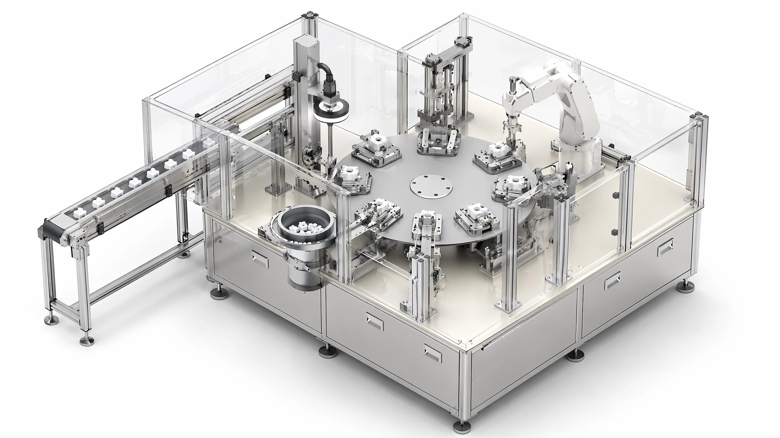
These are multi-station rotary tables with servo-driven indexing, built for high-throughput assembly. Each station performs one operation, whether feeding, insertion, pressing, inspection or sorting, and the rotary table indexes parts between stations with precise positioning.
Design approach: multi-station rotary assembly for medical devices
On a multi-station rotary assembly machine for a small multi-part medical device, we would put vibratory bowl feeders with escapements at the load stations, a servo press at each insertion, machine vision inspection after every operation that can fail, and a SCARA robot at the unload station sorting OK and NG parts on the vision result. Where the product family has variants, the nests and station tooling are made as quick-change sets so a changeover is a swap. The cycle time follows from the slowest station dwell, so the station list is balanced before the dial is sized. How we make each of those decisions, from indexer selection to the records a medical device customer’s quality system needs, is on our page on how we design multi-station rotary assembly machines.
Design features we would specify on such a machine:
- Cam-driven or servo-driven indexing, chosen from the station dwell times
- Vibratory feeders with escapement mechanisms for each component
- Force-monitored insertion stations with data logging
- Multi-point vision inspection (component presence, orientation, dimensional check)
- SCARA robot for output sorting based on vision pass/fail results
Automated Test Equipment (ATE)
These are enclosed testing machines with controlled environments, automated part handling and data logging. ATE systems perform mechanical testing (force, displacement, fatigue), electrical testing (continuity, insulation, functional), or combined testing sequences.
Delivered reference: Cleanroom ATE Series
Motionwell delivered a series of cleanroom ATE systems for electronics testing, each incorporating 4-6 Fan Filter Units (FFU) for ISO Class 7/8 clean air environments. The machines include cobot auto-loading stations, multi-position test fixtures, and PLC control with data logging to CSV and a database. The logging sits in the PLC inside the machine for a reason worth copying: a result that exists only as a file on a desktop machine disappears the first time that desktop is replaced, and on a qualified line it is the missing record that becomes the finding.
These ATE projects demonstrate the intersection of custom machine design and cleanroom requirements, a combination that standard equipment cannot address. The cleanroom ATE case study covers the FFU integration and test fixture design, and our cleanroom automation guide covers the wider constraints.
Special Purpose Machines for Pharmaceutical Production (GMP)
Special purpose machines for pharmaceutical production carry a constraint the other categories do not: the machine has to be provable as well as working. Every sequence it runs has to be reconstructable from records afterwards, which changes the control architecture and the documentation package more than it changes the mechanics.
For pharmaceutical packaging applications, Motionwell has delivered a tray-fed filling and sealing machine and a vial capping and uncapping unit. The filling and sealing machine doses liquid through three diaphragm dispensing heads into containers carried on machined trays, checks the fill level by camera, and seals by heat, press or screw cap. Dose size, fill tolerance and throughput are specification lines on a machine of that type, settled per product against the liquid, the container and the seal method. Two tray stations feed and collect containers so a tray change does not stop the machine.
A GMP (Good Manufacturing Practice) specification for a filling and sealing machine asks for:
- Product-contact surfaces in stainless, with the grade fixed against the cleaning chemistry and the surface finish against the residue limit
- Contact parts and change parts that come off without tools, so cleaning is a written sequence
- Batch record integration with lot tracking
- 21 CFR Part 11 compliant data handling where required
Battery Module Disassembly Equipment
With the growth of battery recycling and second-life applications, Motionwell has developed special purpose machines for battery module disassembly. These machines handle the controlled disassembly of EV battery modules, removing busbars, separating cells, and testing individual cells, with safety interlocks for high-voltage and thermal runaway protection. The battery dismantling case study shows how the safeguarding strategy shapes the layout.
How Does the Design Process Run From Concept to Commissioning?
Phase 1: Concept Design (2-4 Weeks)
The concept phase defines what the machine does without detailing how it does it. The output is a concept document with process flow, station layout, cycle time analysis, and preliminary 3D layout.
| Concept phase deliverable | What it contains |
|---|---|
| Process flow diagram | Step-by-step operation sequence with cycle time per station |
| Station layout | Preliminary 3D arrangement showing machine footprint and operator access |
| Cycle time analysis | Bottleneck identification, index time, and throughput calculation |
| Component list (preliminary) | Major components identified: motors, cameras, robots, PLC |
| Risk register | Technical risks identified with mitigation approach |
| Budget estimate | ROM (Rough Order of Magnitude) cost range |
Motionwell presents the concept for customer review and approval before proceeding to detail engineering. This is the most important checkpoint on the project, because a change made here costs hours and the same change made after detail engineering costs weeks.
Phase 2: Detail Engineering (4-6 Weeks)
Detail engineering produces the full mechanical design (3D CAD), electrical schematics, pneumatic layouts, and control architecture. Every component is specified, every interface is defined, and the BOM (Bill of Materials) is finalized for procurement.
Mechanical design uses SolidWorks for 3D modelling. All parts are designed for manufacturability: CNC machined components use standard tooling, sheet metal follows standard bend radii, and weldments are accessible for inspection. Motionwell’s mechanical designers have direct experience operating CNC machines, which eliminates designs that look good on screen but are impractical to manufacture.
Electrical and controls design specifies the PLC platform, HMI layout, servo drive configuration, safety circuit design, and I/O allocation. The platform is settled against your plant standard, because the consequences of that choice land on your maintenance team and never on ours: a controller nobody on site can program turns every recipe change into a service call, and a second brand on the shop floor means a second set of software licences and a second spares shelf for one machine. The controls architecture includes network layout (EtherNet/IP or PROFINET), safety network topology, and MES/SCADA interface specifications. Where the machine needs a rated safety function, the architecture follows the ISO 13849 and CE marking workflow.
Phase 3: Fabrication and Assembly (6-8 Weeks)
Motionwell has precision components machined to its own drawings by qualified machining partners, sources standard components from approved suppliers, and assembles and integrates the machine in its own Singapore facility. Assembly follows a documented build procedure with quality checkpoints.
| Fabrication method | Typical components | Tolerance capability |
|---|---|---|
| CNC milling | Base plates, mounting brackets, fixture bodies | ±0.01 mm |
| CNC turning | Shafts, bushings, spacers | ±0.01 mm |
| Wire EDM | Precision die components, tight-tolerance slots | ±0.005 mm |
| Sheet metal | Enclosure panels, guards, cable trays | ±0.1 mm |
| Surface treatment | Anodizing (aluminium), passivation (stainless), nickel plating | Per specification |
Phase 4: Testing and Commissioning (2-4 Weeks)
Testing begins at Motionwell’s facility with a Factory Acceptance Test (FAT). The customer witnesses the FAT to verify that the machine meets the agreed specifications for cycle time, accuracy, repeatability, and process capability.
After FAT approval, the machine is delivered, installed, and commissioned at the customer site. Site Acceptance Test (SAT) confirms performance in the production environment with actual production materials.
For regulated industries, commissioning includes Installation Qualification (IQ), Operational Qualification (OQ), and Performance Qualification (PQ) protocols. Motionwell prepares IQ/OQ protocols and supports PQ execution with the customer’s quality team; the evidence each stage requires is set out under computer system validation.
Which Materials Should a Special Purpose Machine Use?
Material selection depends on the operating environment and the product being handled.
| Environment | Frame material | Product-contact material | Surface treatment |
|---|---|---|---|
| General industrial | Mild steel or aluminium extrusion | Depends on product | Powder coat or anodize |
| Electronics / cleanroom | Anodized aluminium (6061-T6) | PEEK, Delrin, anodized aluminium | Hard anodize, Class 3 |
| Pharmaceutical / GMP | SUS304 or SUS316L stainless | SUS316L stainless | Electropolish, with the roughness figure set against the cleaning validation |
| Corrosive environment | SUS316L stainless | SUS316L, PTFE, PVDF | Passivation |
For medical device manufacturing, Motionwell uses materials and finishes selected for product contact and cleaning duty. Compare stainless grades using the cleaning agent, concentration, temperature and contact time, together with corrosion and residue requirements. Document that selection for the actual process; chloride exposure needs evaluation of the complete cleaning regime.
What Control Architecture Should You Specify?
PLC Selection
Motionwell programs the platform your plant already runs, and on a one-off machine that decision is yours to make. Every mainstream platform will run the machine, so the comparison worth having is not a technical one. It is about who maintains the machine afterwards, what they already know, and what they can get hold of quickly.
| What decides the platform | Question to settle before the panel is drawn | What it costs if nobody asks |
|---|---|---|
| Plant standard | Which platform your own technicians already program, and which spares your store already holds | A second toolchain, a second spares shelf and a second support contract for one machine |
| Local support and lead time | Whether controllers, I/O and drives for that platform are stocked in Singapore or shipped in | Weeks of waiting for a part on a line that is already stopped |
| Motion and logic in one environment | Whether the servo drives sit in the same engineering software as the PLC | Two projects to keep in step every time one axis changes |
| Named users and audit trail | Whether the operator interface software can carry named accounts where the process is regulated | A validated line that cannot attribute an action to a person |
| Corporate or customer mandate | Whether a parent company engineering standard has already named a platform | A machine the plant’s own controls group declines to adopt |
HMI Design
The operator interface must be practical. Motionwell designs HMI screens with clear status indication, alarm management, recipe selection, and production data display. Operator training time is treated as a design metric, and the target on our machines is that basic operation can be taught in under two hours.
Servo Systems
Multi-axis servo systems handle indexing, pressing, dispensing, and positioning operations. Motionwell matches the servo drives to the PLC platform so that motion and logic share one engineering environment, which pays off at the first change: a plant that edits a cam profile in the same software it edits the sequence does not need two licences, two engineers and two backup routines to move one axis. Electronic cam profiles replace mechanical cams for flexibility and reduced maintenance. On lower-duty axes the choice between servo and stepper is a real decision, and our comparison of servo versus stepper motors covers where each one belongs.
How Long Does a Special Purpose Machine Take to Build?
| Machine complexity | Typical timeline (concept to FAT) | Example |
|---|---|---|
| Simple (1-3 stations, single axis) | 12-16 weeks | Single-station test fixture with data logging |
| Medium (4-8 stations, multi-axis) | 16-24 weeks | Multi-station ATE with cobot loading |
| Complex (8+ stations, integrated vision/robots) | 24-32 weeks | Multi-station rotary assembly dial (12 stations, for example) with vision and SCARA sorting |
| Regulated (GMP/cleanroom validation required) | Add 4-8 weeks for IQ/OQ/PQ | Filling and sealing machine with 21 CFR Part 11 records |
A recurring schedule risk is late finalization of product design. If the product geometry changes after detail engineering begins, the machine design must change too. Motionwell recommends freezing the product design before Phase 2 starts.
Why Choose Motionwell as a Special Purpose Machine Builder?
Motionwell is a Singapore-based special purpose machine builder with in-house mechanical design, electrical engineering, controls, assembly, and commissioning capabilities. We do not outsource the core engineering, and the team that designs the machine also builds and commissions it. Where a full production line is needed, the same team runs it as a turnkey project.
Our project portfolio spans medical devices, electronics and semiconductor, pharmaceutical packaging, consumer products, and aerospace precision manufacturing. Each industry brings its own requirements, whether GMP compliance, cleanroom compatibility, traceability, or tight-tolerance machining, and we have addressed each of them in delivered projects.
For more details on our custom machine design approach and project references, contact the Motionwell engineering team.
What Should You Send to Start a Project?
If you have a manufacturing process that cannot be automated with standard equipment, the first step is a process review. Contact Motionwell with:
- Product drawings or samples
- Current process description (manual steps, cycle time, quality criteria)
- Production volume targets (parts per hour, shift pattern)
- Quality and regulatory requirements (GMP, cleanroom class, traceability)
- Site constraints (footprint, utilities, ceiling height)
We will evaluate feasibility, propose a concept, and provide a budget range before you commit to a project. Most concept studies are completed within 2 weeks.