
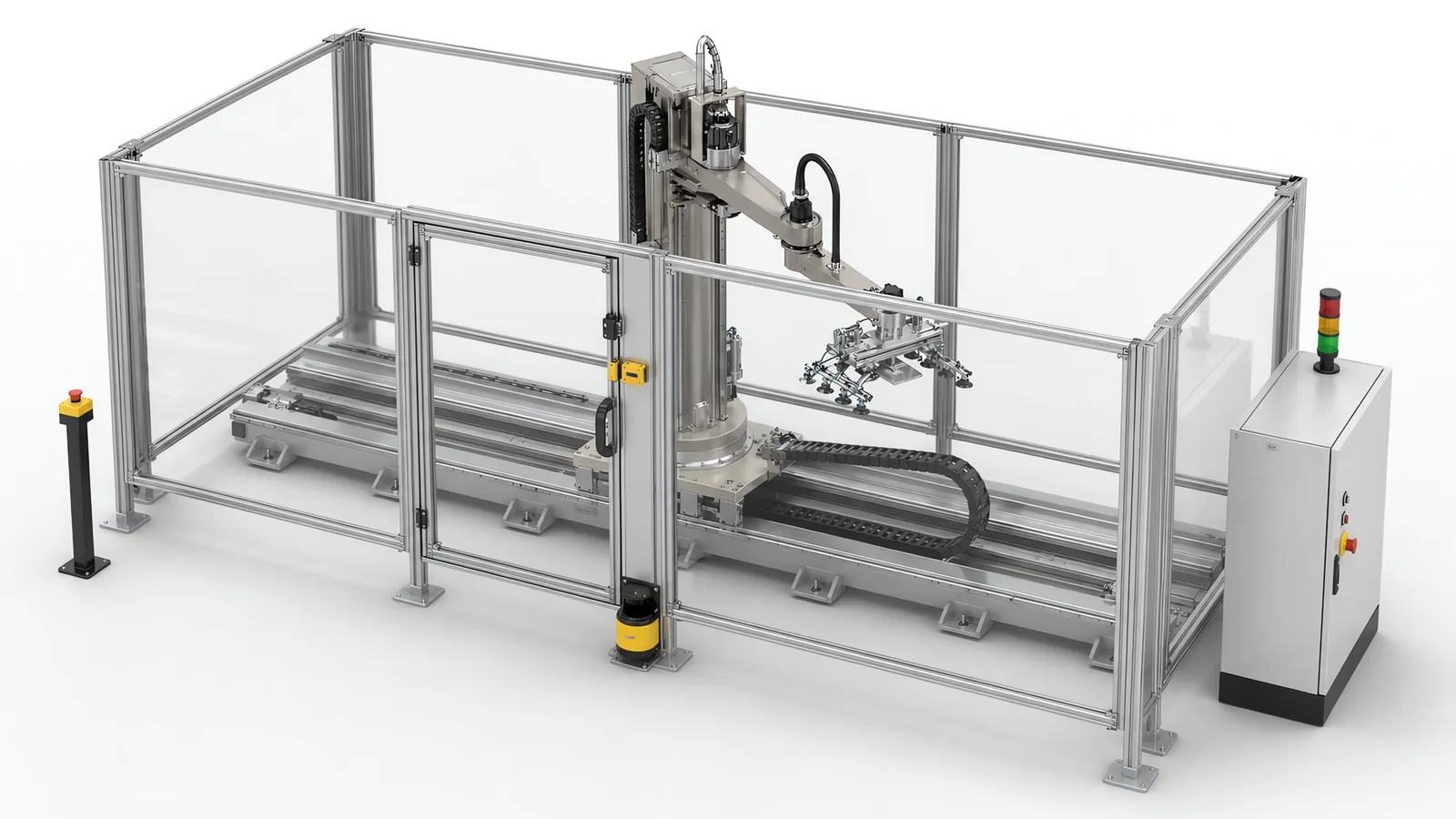
Machine safety work starts with risk assessment and reduction under ISO 12100. Where a protective measure depends on the control system, ISO 13849 provides the route to determine the required Performance Level, design the safety function and validate its performance. Motionwell applies this workflow to the machines we build in Singapore, from interlocked doors and scanners to safety circuits, testing and the technical evidence for handover.
What a machine builder carries is the engineering half: the risk assessment, the PLd architecture, the validation and the technical file. A notified body’s role is separate and third-party certificates are issued there. Any builder who says they “certify” your machine is describing something that does not exist for standard machinery.
If you already have a gap to close, talk to an engineer.
What Are the Performance Levels in ISO 13849-1, and What Does It Require?
ISO 13849-1 covers the safety-related parts of a control system: the sensing, logic and output chain that carries out a protective function. It replaced the category-only thinking of EN 954-1 with a probabilistic approach. For each safety function you state a required Performance Level (PLr) from a to e, then prove the built circuit reaches that level. The levels map to an average probability of dangerous failure per hour:
| Performance Level | Average probability of dangerous failure per hour (PFHd) |
|---|---|
| a | 10⁻⁵ to less than 10⁻⁴ |
| b | 3 × 10⁻⁶ to less than 10⁻⁵ |
| c | 10⁻⁶ to less than 3 × 10⁻⁶ |
| d | 10⁻⁷ to less than 10⁻⁶ |
| e | 10⁻⁸ to less than 10⁻⁷ |
Most industrial functions land on PLc or PLd. PLe is for hazards where a single failure kills and there is no escape. The step that gets argued over on real machines is c to d, because it is the one that changes the hardware: the guard door on the rotary assembly machine example worked through below lands on PLr d, and a function pushed up to that level generally needs a second channel of field devices plus the diagnostics to watch it.
What Is the Most Recent Version of ISO 13849?
The current edition of Part 1 is ISO 13849-1:2023, which superseded the 2015 edition. It is also the edition ISO 10218-1:2025 names for robot control system safety functions, so a cell assessed this year arrives at the 2023 text from either direction, through the machinery route or the robot route.
For an existing machine the consequence is a paperwork one. A design still documented against the 2015 edition needs its performance level calculations restated when the machine is next assessed, and nothing physical has to change for that to be true: the same devices, the same wiring and the same achieved reliability, with only the file out of date. So the safety function register on machines we build records the edition each calculation was made against, next to the PLr and the achieved PL, which turns a restatement into a lookup instead of a re-derivation.
Worth settling before design starts: which edition your contract names. On a machine specified a year or more before it is built, the specification and the standard can already be out of step at kickoff.
How Is the Required Performance Level Determined?
Annex A of ISO 13849-1 gives a risk graph with three parameters. Severity: S1 reversible, S2 irreversible. Frequency and duration of exposure: F1 rare, F2 frequent or continuous. Possibility of avoidance: P1 possible, P2 scarcely possible.
Take a multi-station rotary assembly machine, for example a 12-station dial with servo indexing and press stations, the machine type covered in how we design multi-station rotary assembly machines. A hand in the index path means crushed fingers, so S2. The operator opens the guard for feeder replenishment a few times per shift, so F1. The table indexes faster than a person can withdraw, so P2. That gives PLr d, and the decision sets the circuit design for that door.
Do this per safety function. A multi-station machine typically has six to fifteen of them at different levels, so the emergency stop, the main door, the feeder hatch and the robot scanner each get their own line in the register.
What Does It Take to Reach PLd?
PLd is normally built on a Category 3 architecture: two independent channels, so a single fault does not lose the safety function, plus diagnostics that detect most faults at or before the next demand. Category 3 alone is not enough. The achieved PL also depends on MTTFd per channel (low 3 to 10 years, medium 10 to 30, high 30 to 100), average diagnostic coverage (low 60 to 90%, medium 90 to 99%, high above 99%), and a common cause failure score of at least 65 points on the Annex F checklist.
For electromechanical parts the supplier gives a B10d value. You convert it using the real number of operations per year, which is why the same contactor is fine on a door opened twice a shift and marginal on one that switches on every index of a fast dial. Any component whose T10d falls short of the mission time goes into the maintenance plan as a scheduled replacement.
A PLd door circuit on our machines: a coded RFID interlock with dual OSSD outputs, a safety controller, and two contactors with mirrored auxiliary contacts fed back for external device monitoring. Cross-fault detection comes from the OSSD test pulses, and the calculation is kept as a SISTEMA project file so it can be re-checked when a component is substituted.
How Do You Run a Machine Risk Assessment?
ISO 12100 gives the method. First determine the limits: space, expected life, every operating mode including setup, cleaning, fault clearing and maintenance, and reasonably foreseeable misuse. Setup and fault clearing are where most injuries happen, because that is when guards get opened and hands go where the designer never pictured them going.
Then identify hazards and reduce risk in strict order: inherently safe design first, safeguarding second, information for use last. Moving a pinch point out of reach costs nothing at concept stage and removes the hazard permanently.
| Hazard on machines we build | Typical measure, in priority order |
|---|---|
| Servo index table, press and gripper crush points | Enclose the motion path; interlocked door to PLd; guard locking where run-down exceeds access time |
| Robot envelope and 7th-axis linear track | Perimeter guard plus safety laser scanner on the load side; reduced speed in teach mode |
| Abrasive blasting media and rotating spindle | Sealed cabinet, interlocked door with locking, extraction interlocked to start |
The output is a register: hazard, operating mode, S/F/P rating, measure, PLr, and the residual risk that goes into the handbook.
Selecting the logic device is a separate decision within that function design. Our safety PLC selection guide compares controller architectures and the validation work around the complete sensing-to-output chain.
What Goes into Custom Machine Guarding?
Custom machine guarding starts with reach. ISO 13857 sets the safety distances for reaching over, under, around and through openings, which fixes mesh aperture against standoff distance. ISO 13855 governs scanner and light curtain positioning: minimum distance comes from the approach speed constant K, taken as 2000 mm/s up to 500 mm and 1600 mm/s beyond, plus total system stopping performance and a penetration factor. Guess it and you build a guard that looks right and stops too late.
ISO 14119 covers the interlocking devices, including how hard each is to defeat. Coded magnetic and RFID switches go anywhere an operator has a production reason to want the door open. If run-down time after the stop command exceeds the time it takes to reach the hazard, the guard needs locking, released by a standstill monitor.
On the cleanroom automated test equipment the guard enclosure also carries the fan filter units and has to preserve downward airflow, so it is part of the process design: see the cleanroom ATE case study. On packaging machines the guard passes material in and goods out without giving a hand a route in, which is what muted openings are for.
The machine guarding design page develops these decisions opening by opening, including fixed panels, interlocked access, material transfer and containment. Use the resulting guard layout alongside the safety function register and validation plan.
What Do OSHA Machine Guarding Requirements Add?
OSHA regulates the employer operating the machine; CE marking regulates the product placed on the European market, so a machine can be fully CE marked and still fail a US plant’s internal audit.
For a US site the references are 29 CFR 1910.212 for general machine guarding, 1910.219 for power transmission apparatus and 1910.147 for hazardous energy control, backed by ANSI B11 and ANSI/RIA R15.06 for robots. The differences land on the electrical build: NFPA 79 in place of IEC 60204-1, a lockable main disconnect, identified isolation points for every energy source, and a lockout procedure the EHS team can adopt as written. We ask which market a machine ships to before panel design starts.
What Changes When a Collaborative Robot Is Involved?
ISO 10218-1 covers the robot itself; ISO 10218-2 covers the robot system and its integration, which is the part a machine builder owns. ISO/TS 15066 added the biomechanical detail for collaborative applications, and the 2025 revision of ISO 10218 folded much of that guidance into the standards.
Assess the robot with its tooling, payload, fixtures and access tasks. A sharp gripper, heavy payload or hazardous workpiece may make contact-based power and force limiting unsuitable. Other operating modes can maintain protective separation or hold the robot stopped while a person enters. The collaborative methods include:
- Safety-rated monitored stop: the robot holds position while a person is in the shared space and resumes only when it is clear
- Hand guiding: motion commanded through a hand-guiding device with an enabling switch and a safety-rated speed limit
- Speed and separation monitoring: the robot slows and stops as a person approaches, with separation distance calculated from approach speed, robot speed, measured stopping distance and sensor uncertainty
- Power and force limiting: contact is permitted but limited, with limits verified by force and pressure measurement against body-region values
Separation distance is not fixed: it shrinks as the robot slows, so scanner zones, speed profile and stopping distance are one coupled problem.
Workpiece hazards affect the protective measures: our battery disassembly systems use fenced stations, while the QA Lab Transformation programme combines AMR scanning, traffic zones and station-level assessment of the arm, gripper and sample. Lab staff continue working in the room.
Our robot integration work includes customer-supplied arms. For each arm, obtain the OEM safety manual and evidence for the safety functions used in the cell, including their rated performance and integration conditions. Separately, measure stopping behaviour with the installed tool, load and operating speeds. A site stop test supplies distance and time evidence; the OEM documentation supports the function’s reliability and correct integration. If records are incomplete, recover them from the supplier and assess the protective architecture before selecting the safety functions. The cobot applications page explains mode selection for shared workspaces.
What Does CE Marking Machinery Involve?
CE marking is a self-declaration process for most machinery, supported by evidence:
- Determine which legislation applies. Machinery Directive 2006/42/EC applies until 19 January 2027, after which Machinery Regulation (EU) 2023/1230 takes over, alongside the EMC Directive and, for some equipment, the Low Voltage Directive.
- Check whether the machine appears in Annex IV. Most custom production machinery does not, so conformity assessment is by internal production control with no notified body involved.
- Apply harmonised standards: EN ISO 12100, EN ISO 13849-1, EN 60204-1, plus the relevant type-C standard if one exists.
- Compile the technical file, issue the Declaration of Conformity, affix the mark.
Two points are worth settling before design starts. First, who is the manufacturer in the legal sense: if the customer assembles our machine into their own line they may become the manufacturer of the assembly, with our machine supplied under a declaration of incorporation. Second, retrofits: modernising the PLC, servos and drives on a legacy machine can amount to a substantial modification, which puts the modifier in the manufacturer’s position. That belongs in the kickoff meeting.
Where accredited LVD and EMC test reports are needed we arrange testing with an external laboratory and fold the reports into the file. We implement and document; the test house tests.
What Applies to Machines Installed in Singapore?
Singapore does not require CE marking, but the Workplace Safety and Health Act requires dangerous parts of machinery to be securely fenced and places duties on the occupier and on anyone supplying machinery for use at work. Most multinational manufacturers here specify CE conformity as an internal standard anyway. The local requirement builders miss is lifting: machines that incorporate lifting equipment must be examined and certified by an approved authorised examiner before use, with periodic re-examination after. Motionwell handles this as part of delivery, alongside LVD and CE testing.
How Is the Safety Function Validated Before Handover?
ISO 13849-2 requires validation by analysis and by testing. Analysis checks that the built circuit matches the design, that the calculated PL holds with the components fitted, and that fault exclusions are justified. Testing is where the problems surface:
- Fault injection. Open one channel of a dual-channel circuit. The machine must stop, the fault must be annunciated, and restart must need a deliberate reset.
- Stopping time measurement. Measure real system stopping performance, then confirm the scanner and light curtain distances from ISO 13855 still hold. This is the most important test after a control-system retrofit, because a new servo drive on old mechanics changes run-down time in ways no datasheet predicts.
- Reset and restart interlock. The reset device sits outside the hazard zone with full view of it, and the machine must not restart on guard closure alone.
- Modes and manual measures. Muting logic checked against the material profile it should accept, teach mode checked to confirm it limits speed, emergency stop reach checked from every operator position, and energy isolation verified by attempting a movement with the isolator locked off.
What Is in the Documentation Pack?
The file is the deliverable that survives after the commissioning engineer leaves: the ISO 12100 risk assessment, the safety function register with PLr and achieved PL, the calculation record, safety circuit schematics, safety distance calculations, the ISO 13849-2 validation report, stopping time records, supplier reliability data, the instruction handbook, the Declaration of Conformity, and any LVD, EMC or lifting certificates. On medical device and pharmaceutical builds this evidence is referenced from the IQ and OQ protocols, so the quality team keeps one set of records.
What Drives the Cost of Machine Safety?
There is no price list for this, and it would not help if there were. Most of the number is fixed by decisions taken before any hardware is ordered:
- Number of safety functions. Each access point, each mode, each robot zone is its own circuit and its own calculation.
- Required Performance Level. Moving a function from PLc to PLd usually doubles the field devices and adds diagnostics. Specify PLe everywhere and you pay everywhere.
- Guard area, geometry and locking. Enclosure cost scales with the perimeter you chose at layout, and long run-down times force guard locking where a plain interlock would do.
- Sensing and external testing. Scanner zones, muting and multi-beam arrays add configuration and validation time; accredited EMC and LVD testing carries external cost and lead time.
- Retrofit archaeology. On legacy machines the control system is often undocumented, and working out what the existing circuits do before replacing them is frequently the largest single item in a retrofit safety scope.
The cheapest safety decisions are layout decisions. Fewer access points, a feed path that needs no hand inside, and short run-down times save more than any component choice later. That is why safety belongs in concept design, where it sits in our machine design process.
Standards Used in Machine Design and Validation
These references inform the design, testing and documentation described on this page. Each row links to its primary source and records the edition checked.
| Standard | Current edition | What it means for your machine |
|---|---|---|
| ISO 13849-1: Safety of machinery, safety-related parts of control systems | ISO 13849-1:2023 | Provides the design method for safety-related control functions, including architecture, component reliability, diagnostic coverage and common-cause failure measures. The machine risk assessment establishes the required Performance Level; design calculations and validation provide the evidence for each function.Checked 1 Sep 2026 against ISO 10218-1:2025 normative references |
| ISO 10218-1: Robotics, safety requirements, Part 1: industrial robots | ISO 10218-1:2025 | Published February 2025, the third edition and the first substantive revision since 2011. It adds robot classifications with matching functional safety requirements and safety-related cybersecurity requirements. Most of ISO/TS 15066:2016 on collaborative operation moved into Part 2.Checked 12 Sep 2026 against ISO 10218-1:2025 (iso.org/standard/73933.html) |
| Regulation (EU) 2023/1230: the EU Machinery Regulation | (EU) 2023/1230 (changeover pending) | Applies on a mandatory basis from 20 January 2027, replacing Machinery Directive 2006/42/EC. Project planning should align the intended EU market date with the conformity assessment and technical documentation, including relevant software integrity and connected-function requirements. The European Commission permits voluntary declarations against the Regulation before that date, while the Directive remains applicable.Checked 1 Sep 2026 against European Commission, Machinery page (single-market-economy.ec.europa.eu/sectors/mechanical-engineering/machinery_en); EU-OSHA legislation register |
Updates to this page
-
Added a table of the standard editions we currently design against. The one carrying a hard date is Regulation (EU) 2023/1230: it replaces Machinery Directive 2006/42/EC for machines placed on the EU market from 20 January 2027, with no transitional period. It is also the first EU machinery law to put software integrity and connected functions alongside mechanical safety, which changes the documentation for a networked line.
Frequently Asked Questions
What is machine safety?
Machine safety is the engineering work that makes a machine safe to run, set up, clean and repair, done by the builder before it ships, and never by procedures written afterwards. The method is ISO 12100: determine the limits and every operating mode, identify the hazards, then reduce risk by inherently safe design first, safeguarding such as fixed guards, interlocked doors and scanners second, and information for use last. Whatever the mechanical measures cannot remove is carried by the control system, and ISO 13849-1 sets how reliable that part has to be. The employer's duties on the plant floor, training, procedures and lockout, sit alongside this and do not substitute for it.
What is ISO 13849 and how does it differ from ISO 12100?
ISO 12100 is the method for assessing and reducing machine risk overall. ISO 13849-1 covers only the safety-related parts of the control system that carry out a protective function, such as a guard door circuit or a scanner stop. ISO 12100 tells you a hazard needs a control-based measure; ISO 13849-1 tells you how reliable that measure must be, expressed as a required Performance Level from a to e, and how to prove the circuit reaches it.
How do you determine the required Performance Level (PLr) for a safety function?
Use the Annex A risk graph in ISO 13849-1 with three parameters: severity of injury (S1 reversible, S2 irreversible), frequency and duration of exposure (F1 rare, F2 frequent), and possibility of avoiding the hazard (P1 possible, P2 scarcely possible). A servo indexing table where a trapped hand means irreversible injury, the operator opens the guard a few times per shift, and the motion is too fast to escape gives S2/F1/P2, which lands on PLr d.