
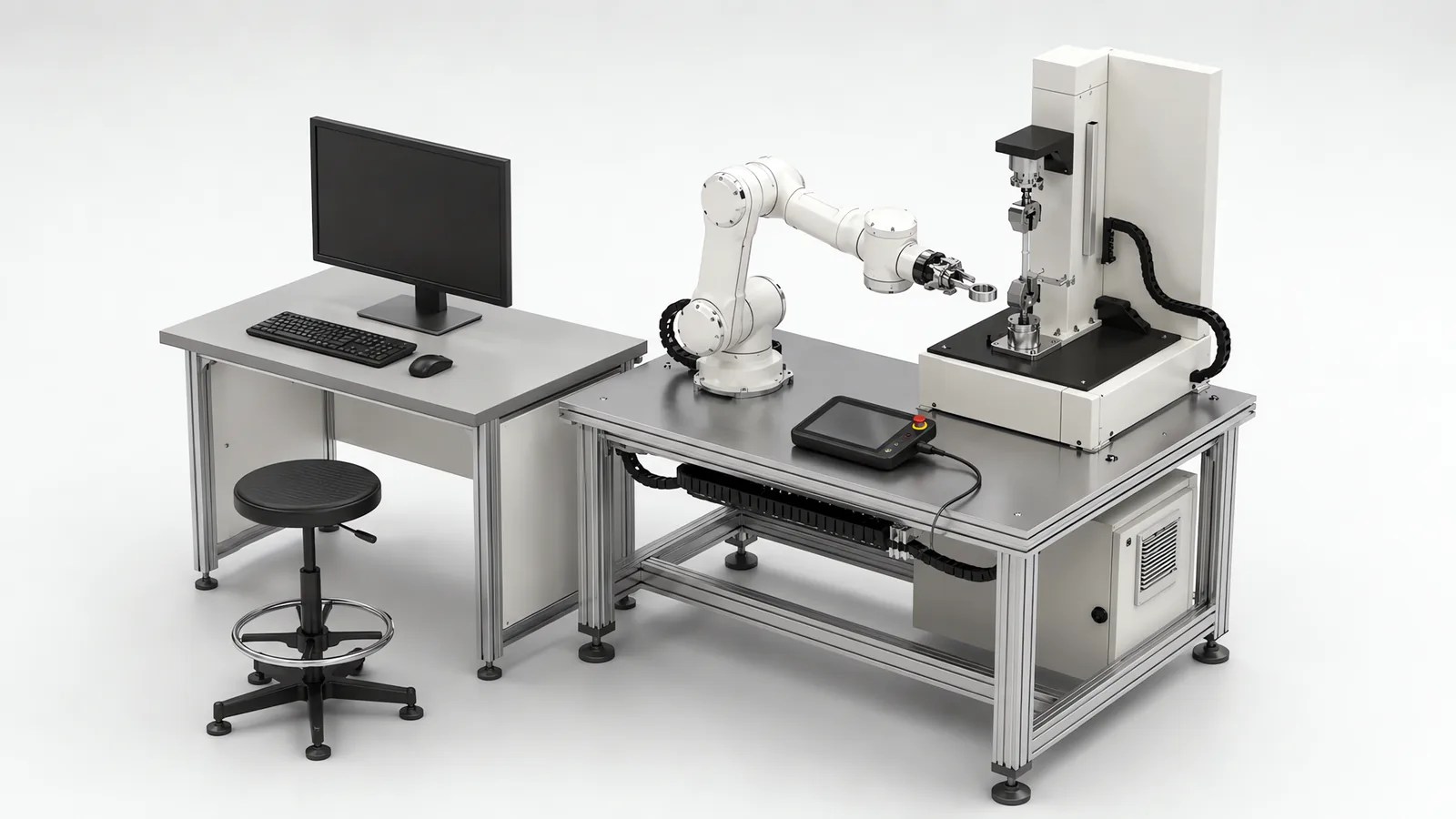
Motionwell Automation designs and integrates collaborative robot cells in Singapore, including applications built around customer-supplied arms. Cobot integration combines robot selection with tooling, part presentation, controls and safeguarding. The real tool, workpiece and access tasks determine the permitted speeds and operating modes.
Delivered applications include an AMR-mounted arm tending QA laboratory instruments, a consumer-goods unloading station and overhead arms for pick-and-place and capping. These cells are designed, assembled and tested at Woodlands Link.
A collaborative application is assessed with the real arm, tooling, workpiece, speeds, fixture and people who share the space. Sharp tooling or a heavy part may rule out contact-based power and force limiting while leaving separation monitoring or a monitored stop as possible safeguards. Where robot motion limits the cycle, a fenced industrial arm may offer more throughput. Compare the complete cycle, including instrument dwell and part handling, before choosing the architecture.
The wider safety workflow sits on our machine safety and CE marking page and in our note on collaborative robot safety standards.
What Makes an Application Collaborative, and Not the Robot?
A collaborative robot, usually shortened to cobot, is an industrial robot arm built to work in a shared space with people, with safety-rated functions in the arm itself: monitored speed, monitored position, monitored force or torque, and a stop architecture that can be relied on. That is the product definition, and it describes the arm as it is sold and certified, on its own, with nothing on the flange and nothing in the gripper. Those functions are real and worth paying for. Your cell is the arm plus a tool, a part, a fixture, a bench edge and a person, and any of those can carry the hazard.
Four common conditions need particular attention before choosing contact-based power and force limiting:
- The tool is the hazard. A blade, a hot tip, a screwdriver bit, a probe, a thin nozzle. Small contact areas concentrate pressure, and some geometries cannot pass a contact assessment at any usable speed.
- The workpiece is the hazard. A sharp-edged pressing, a glass container, an energised assembly. On the battery line below, the pack is live and the arm is the least dangerous object in the cell.
- The payload is the hazard. Force limiting governs what the arm does to a person. It says nothing about a part dropped on a foot.
- The geometry is the hazard. A hand trapped between the tool and a fixed surface cannot move away, and the standards assess that case more strictly than a free impact. The fixture layout creates it.
Sorting this out uses the ordinary machinery method. ISO 12100 fixes the order of risk reduction: inherently safe design first, safeguarding second, information for use last. A cobot cell is still a robot system, so ISO 10218-1 covers the robot and ISO 10218-2 the integrated system, which is the part a machine builder owns. Most real cells therefore end up hybrid: collaborative behaviour at the one station where a person needs to be, physical safeguarding where the risk actually sits.
What Are the Four Types of Collaborative Operation, and What Does Each Permit?
Four modes are recognised, with no ranking among them. Most cells use more than one in sequence, because the robot does different things at different moments in the cycle.
| Mode | What it permits | What the cell needs | What it costs |
|---|---|---|---|
| Safety-rated monitored stop | Holds position while a person is in the shared space, resumes when it is clear. Suits occasional intervention: reloading a tray, clearing a jam | Safety-rated presence sensing, monitored standstill, restart logic | All throughput while a person is present. Cheap if intervention is rare |
| Hand guiding | Motion commanded through a guiding device with an enabling switch and a safety-rated speed limit. Suits teaching, setup, lifting assistance | Enabling device, reduced-speed mode, emergency stop in reach | An operator present for every motion, so it does not scale to production volume |
| Speed and separation monitoring | Runs fast when nobody is near, slows and stops as a person approaches. Suits shared aisles with predictable traffic | Safety scanners, zoned speed profiles, measured stopping performance, floor space | Floor area and sensing. It fails safe by stopping, so a busy aisle stalls the cell |
| Power and force limiting | Contact permitted but bounded, so it stays within body-region limits. Suits close interaction through most of the cycle | Verified force and pressure measurement with the real tool and part, rounded tooling | Cycle time, permanently. The speed cap is the mechanism |
Mode selection is a question about people. Ask how often someone is truly inside the space and what they do there. Reloading a tray twice a shift makes a monitored stop simpler, cheaper and faster than tuning force limits. An operator working alongside the arm all shift makes power and force limiting the only mode that will not destroy the cycle time. And if the hazard is the gripper or the part, no mode fixes it: that hazard needs safeguarding of its own.
Should You Specify Speed and Separation Monitoring or Power and Force Limiting?
These two carry most production cobot cells, chosen for opposite reasons. One buys speed at the cost of floor area and sensing. The other buys proximity at the cost of speed.
| Speed and separation monitoring | Power and force limiting | |
|---|---|---|
| Underlying idea | Never touch. Hold a separation distance that shrinks as the robot slows | Touching is allowed, but bounded by measured limits |
| What is engineered | Sensing coverage, zone geometry, speed per zone, stopping performance | Tool and part geometry, contact area, speed cap, verified force and pressure |
| Speed when nobody is near | Full application speed | Still capped, because limits apply whenever a person can be present |
| What defeats it | Cluttered floors, forklifts, a separation distance the room cannot give you | A tool or workpiece geometry that cannot pass a contact assessment |
| Floor area | Significant, and it is floor you cannot fill with pallets | Minimal, often the real reason it gets specified |
| Validation evidence | Stopping distance measurements, scanner zone verification, safety-distance calculations | Force and pressure records at each credible contact point, by body region |
| Best fit | Machine tending and transport, where a person passes through occasionally | Assembly, inspection loading and lab tending, with a person beside the arm |
The detail worth checking in any quotation is that the separation distance is not a number to be looked up. It comes from the approach speed of a person, the robot’s current speed, the measured stopping distance of the whole system and the uncertainty of the sensing, so zones, speed profile and stopping performance are one coupled problem. Sensor positioning on our machines follows ISO 13855, which sets the approach speed constant at 2000 mm/s up to 500 mm and 1600 mm/s beyond. Guess it and you build a cell that looks right and stops too late.
One argument for power and force limiting is easy to miss on a datasheet: its safety case is built around the tool, the part and the surfaces near the arm. Separation monitoring draws its zones against a layout, so a pallet stand left standing in a scanner zone trips the scanner and stalls the cell, and the safety case is lost at the moment someone reshapes the zone around the obstruction.
How Are Force Limits Verified, and What Sets Them?
They are verified by measurement on the built cell, with the actual end effector and the actual workpiece on it. The arm’s published figures cannot stand in for that measurement, because they are established on the bare arm, before your tool and your part are on it.
Force and pressure are two different results. Pressure is force divided by contact area, so a gripper finger with a small radius, a part corner, or the tip of a screwdriver bit can fail a pressure limit at a force that passes with room to spare. Rounding an edge to increase the contact patch is often the cheapest fix available, and it costs nothing at concept stage.
Contact type changes the limit. The standards draw a distinction here: transient contact, where a person can move away, is assessed separately from quasi-static contact where the body is held between the moving tool and a fixed surface, and the quasi-static case is the more restrictive of the two. The layout creates that case: a bench, a fixture wall, a conveyor rail. Half the design work in a force-limited cell is removing the surfaces a hand could be pinched against.
Limits are body-region specific. Contact acceptable against a forearm is not necessarily acceptable against a hand or a face, so measurement is taken where contact is credible given the arm’s reach and the operator’s posture.
So the tooling and the workpiece set the limit. Across our medical device and electronics assembly work, redesigning a gripper after commissioning costs several times more than addressing it at concept review, and a compliant fingertip or a rounded bracket edge can move a contact scenario from unacceptable to acceptable without touching the robot program.
So design the tool against the contact assessment at the same time as against the part, and treat the evidence as a test plan written at concept stage, and never a report written afterwards. On regulated lines it is referenced from the equipment qualification protocols, the discipline described on our computer system validation page. Each safety function is rated for performance level under ISO 13849-1, as on any other machine.
Which Applications Does a Cobot Genuinely Earn Its Place In?
The test that settles it is whether a person is really in the space, doing something a machine cannot cheaply take over, for a meaningful part of the cycle. If not, the collaborative premium buys nothing.
| Application | What the arm does | What usually sets the limit |
|---|---|---|
| Machine tending | Loads and unloads a machine that would otherwise wait for an operator between cycles | Part edges and swarf. For high-duty tending across many machines we have used linear gantry systems instead, because reach and duty beat proximity |
| Laboratory instrument tending | Loads specimens into instruments, retrieves them, returns them to a rack | The instrument’s control interface. An instrument with no accessible interface is the project risk |
| Inspection and vision-station loading | Presents a part to a camera at a repeatable position and orientation, then sorts on the result | Presentation repeatability and lighting access. The arm is now part of the optical setup |
| Dispensing | Carries a dispense valve along a path, or presents the part to a fixed valve | Path speed stability, and the material. A heated or reactive material is a hazard the arm cannot limit |
| Packaging, unloading and decanting | Moves units between cartons, totes and trays where the pattern changes per SKU | Tooling versatility and pitch adjustment. Cycle rate is usually the ceiling |
| Screwdriving and fastening | Drives fasteners to a recorded torque on a part a person also works on | The bit. A protruding driver tip concentrates the whole contact force onto a very small area, which is precisely what the assessment measures |
Palletizing beside an operator belongs there too, limited by rate and reach, and our palletizing systems page works it through. The delivered work behind several of those rows is worth being specific about.
In a QA laboratory for a medical device manufacturer, a collaborative arm on an autonomous mobile robot retrieves samples from storage, loads them into universal testing machines and returns them, under a warehouse management layer running natively in the machine PLC, managing 70 positions across 7 racks. Keeping the rack map and the job queue inside the controller means there is no middleware to validate, no second computer to patch, and no disagreement between two systems about which position a sample is in when the network drops; the price is that a rack layout change becomes a PLC change, so the tag structure has to be built to be edited. Technicians work in the same room throughout, which is why the cell is collaborative. The build is in the QA lab automation case study, the architecture around it on our laboratory automation capability page.
At a consumer goods distribution centre, a cobot unloading station decants mixed SKUs from cartons into tote bins with a 5-magnet electromagnet quick-change tool that switches between gripper and vacuum modes on its own, and X and Y pitch adjustment on stepper motors so one tool covers several product sizes without a mechanical changeover. It reads the carton ID at the infeed and reconfigures from a tool change rack, as set out on the FMCG and co-packing automation page. Where floor area is the constraint we mount the arms overhead for pick-and-place and capping, freeing the floor for conveyors and operator access at the cost of harder maintenance access and a mounting frame stiff enough that the arm’s own reaction torque does not move the tool point. The capping version uses a custom end-of-arm tool with pneumatic torque control and cap presence verification, described on the capping and sealing systems page.
One boundary on screwdriving. Fastening is well within scope: on our SCARA sensor panel assembly line, torque-controlled electric screwdrivers work to a target set per fastener in the recipe, with the result logged against the panel serial number. That instrumentation transfers to a collaborative arm unchanged. The safety case does not, because a driver bit is the small-radius protruding geometry contact assessments struggle with, so that station may need guarding even in an otherwise collaborative cell.
What Changes When the Cobot Rides on a Mobile Base?
The assessment expands to cover travel and every docking station. ISO 3691-4 addresses the driverless industrial truck and its operating zones; ISO 10218 addresses the industrial manipulator and its application. The combined assessment covers the transition between travelling, docking and arm movement.
| Fixed-base cobot cell | Cobot on a mobile base | |
|---|---|---|
| Where the collaborative space is | One location, drawn on the layout, assessed once | Wherever the vehicle is, plus everywhere it travels between stations |
| What the assessment covers | The cell, its tooling, its workpieces and its access points | The vehicle in transit, plus every docking station as its own application |
| Who protects the person | The cell’s own sensing and guarding | On-board scanning while driving, the station assessment while working: two cases that must not overlap |
| What breaks it later | A new fixture or a changed part | A moved bench or rack, a pallet in the aisle. The floor is not under the robot’s control |
Two design rules keep this tractable. Sequence the base and the arm, never driving and reaching at once, so the two safety cases do not have to be superimposed. And treat each docking station as its own application, never approving “the robot” once, because the station determines who stands nearby and what the arm can reach. The QA laboratory system is layered accordingly: on-board scanning while the vehicle drives, defined traffic zones on the lab floor, and a cell-level assessment at each station covering the gripper and the sample.
On the laboratory system, SLAM navigation gets the vehicle to within about plus or minus 50 mm. Arm positioning repeats to within plus or minus 0.1 mm at the tool centre point relative to the parked base. A wrist camera reads tray or fixture fiducials and corrects the X, Y and theta offset before each pick and place, bringing final placement to within plus or minus 0.5 mm. This correction accommodates docking variance and station movement within the calibrated working range. Our AMR and AGV integration page explains the station interfaces and fleet commissioning.
Cobot vs Industrial Robot: Where Is a Fenced Arm the Better Answer?
Cobots are oversold, and five situations put the better machine behind a fence. We build cells both ways, so the comparison below is the one we run at concept review.
The hazard is the workpiece. Our EV battery dismantling line is the clearest example we have. The disassembly stations use two fenced industrial robots at 200 kg payload and 2.6 m reach, with every safety function engineered to ISO 13849 Performance Level d. The packs are live at 400 V and above, the end effectors are insulated, and collaborative rules were deliberately not used to justify an open cell. Force limiting has nothing to say about high voltage. The EV battery dismantling case study sets out the reasoning.
Cycle time dominates. A power-and-force-limited application has its speed capped so contact stays inside the limits. That cap is the technology, and it is where the rate ceiling comes from. You do not get around it with a faster arm; you get around it by adding guarding and speed, at which point you have a small industrial cell with an expensive arm in it. The rule of thumb on end-of-line work is simple: at three shifts, or at a rate above what one arm holds on a single pick, the industrial robot is the cheaper machine to own.
The tooling cannot be made safe. Long, thin or pointed end effectors concentrate pressure, and some geometries cannot pass a contact assessment at any useful speed. Redesign the tool if you can; if the process needs that geometry, guard it.
Nobody is actually present. A cell running lights-out gains nothing from collaboration and loses throughput. Check who is genuinely inside the space before the arm is ordered, because a cobot bought for an unattended cell pays the collaborative speed cap for nothing.
Reach or payload is the constraint. Rated payload assumes the load sits close to the flange, and a tool holding a part out from the wrist creates a moment that limits the arm long before mass does. Read the payload-versus-centre-of-gravity chart at the real tool centre of gravity and the real reach. If the heaviest part only just fits, it does not fit.
What Do We Supply on a Collaborative Cell, and What Do We Buy In?
Arms are bought in and integrated, and the arm gets chosen after the application is settled: whether the duty is genuinely collaborative or only looks it, the payload at the real tool centre of gravity, the reach from wherever the base can park, the footprint you can give up, and whether a plant standard with local spares already exists. Where a customer has already standardised on an arm we build the cell around that arm, because a second brand on the floor costs more in spares, training and programming support than the price difference on one purchase order.
What we design and build is everything between the arm and your product: the end-of-arm tooling, the fixtures and part presentation, the station frame, the safeguarding and safety circuit, the PLC and HMI, the recipes, and the data the cell produces. Grippers are catalogue units where one fits the part and tooling designed in-house where none does, which is the more common outcome on a part with a soft, wet or irregular gripping face. Vision is bought in and then lit and calibrated per application, because on a handoff or an inspection step the lighting and the fixture decide whether the reading repeats and no camera recovers a badly lit scene, as covered on our machine vision inspection page.
The conformity work is implemented and documented here, with accredited LVD and EMC testing arranged at an external laboratory.
Which Standards Does a Collaborative Cell Have to Answer To?
One change is worth knowing before you write a specification this year. ISO 10218 was revised in 2025, and most of what ISO/TS 15066:2016 said about collaborative operation now sits inside ISO 10218-2, and no longer in a separate technical specification. The engineering does not change; which document your contract and safety file name does. Where the cell is partly guarded, the ordinary standards still decide the physical design: ISO 13857 for reach distances, ISO 13855 for scanner and light curtain positioning, ISO 14119 for interlocking devices and how hard each is to defeat.
For machines installed in Singapore, CE marking is not a legal requirement, but the Workplace Safety and Health Act requires dangerous parts of machinery to be securely fenced and places duties on the occupier and on anyone supplying machinery for use at work. Most multinational manufacturers here specify CE conformity as an internal standard regardless. Where the machine ships into the EU, the European Commission’s machinery framework is what the technical file answers to, with the workflow on our machine safety compliance page.
How Much Does a Cobot Cell Cost in Singapore, and What Drives It?
Two cells that look identical on a layout can differ by a wide margin, and the difference is decided before any hardware is ordered. It sits in the seven decisions below far more often than in the arm.
| Cost driver | Why it moves the number |
|---|---|
| Collaborative mode selected | Separation monitoring buys sensing and floor area; force limiting buys measurement, tooling redesign and cycle time |
| End-of-arm tooling scope | One part geometry is a component-selection job. Several formats on one tool, or a quick-change rack, is a design project |
| Part presentation | A part arriving in a fixture is cheap. A part in a bin or an arbitrary pose is a vision and tooling problem first |
| Contact assessment difficulty | Sharp, hot, heavy or awkward workpieces push the cell toward guarding, which changes the whole architecture |
| Machine or instrument interfaces | Digital I/O or an Ethernet command set is cheap; a device with only an operator GUI costs real engineering |
| Mobile base | A moving collaborative space means per-station assessment, docking correction, and recovery logic that works with the vehicle anywhere on the floor |
| Safeguarding and validation scope | Scanner zones, stopping distance measurement, force and pressure records, and the documentation holding them |
Lead time runs 16 to 24 weeks from concept approval to factory acceptance testing on a standard build, and 24 to 32 weeks where cleanroom compatibility or full validation documentation applies. Design, assembly and testing happen at Woodlands Link, so a Singapore buyer attends the acceptance test without flying to it. That matters more on a collaborative cell than on most machines, because the acceptance test is where your operators find out whether the recovery behaviour is something they will live with or defeat by the third shift. How a build of this shape is scoped is covered in our guide to special purpose machine design.
Standards Used in Machine Design and Validation
These references inform the design, testing and documentation described on this page. Each row links to its primary source and records the edition checked.
| Standard | Current edition | What it means for your machine |
|---|---|---|
| ISO 10218-1: Robotics, safety requirements, Part 1: industrial robots | ISO 10218-1:2025 | Published February 2025, the third edition and the first substantive revision since 2011. It adds robot classifications with matching functional safety requirements and safety-related cybersecurity requirements. Most of ISO/TS 15066:2016 on collaborative operation moved into Part 2.Checked 12 Sep 2026 against ISO 10218-1:2025 (iso.org/standard/73933.html) |
| ISO 13849-1: Safety of machinery, safety-related parts of control systems | ISO 13849-1:2023 | Provides the design method for safety-related control functions, including architecture, component reliability, diagnostic coverage and common-cause failure measures. The machine risk assessment establishes the required Performance Level; design calculations and validation provide the evidence for each function.Checked 1 Sep 2026 against ISO 10218-1:2025 normative references |
Frequently Asked Questions
Does buying a collaborative robot mean the cell needs no guarding?
Guarding follows the application risk assessment, which covers the arm, tooling, workpiece, speeds, fixture and people together. Many cells combine collaborative operation at an operator-facing station with physical safeguarding elsewhere. A sharp tool, hot part or heavy payload may make contact unacceptable; protective separation or a monitored stop can keep people clear of that hazard. The selected operating modes determine the guarding and validation work.
How are cobot force and pressure limits actually verified?
By measurement on the built cell, with the real tooling and the real workpiece, and never from the arm's published limits. Force and pressure are two separate results, because pressure is force divided by contact area, so a small radius on a gripper finger or a part edge can fail a pressure limit at a force that passes comfortably. Contact type matters as well: the standards separate transient contact, where the body can move away, from quasi-static contact against a fixture or a wall, and the quasi-static case is the more restrictive of the two. Those records, plus scanner zone verification and stopping distance measurements, are the validation evidence for the cell.
Can a collaborative robot be mounted on a mobile robot base?
Yes, and we have delivered it: a QA laboratory system where an autonomous mobile robot carries a collaborative arm between sample racks and several test instruments, re-ordered by the customer after the first build. What changes is the safety case, because the collaborative space moves with the vehicle. The assessment stops being one fixed floor area and becomes the vehicle in transit plus every station it docks at, each with its own surroundings and its own bystanders. Positioning changes too. Navigation lands the base within about plus or minus 50 mm, so the arm needs a vision correction step before it commits to a pick.