
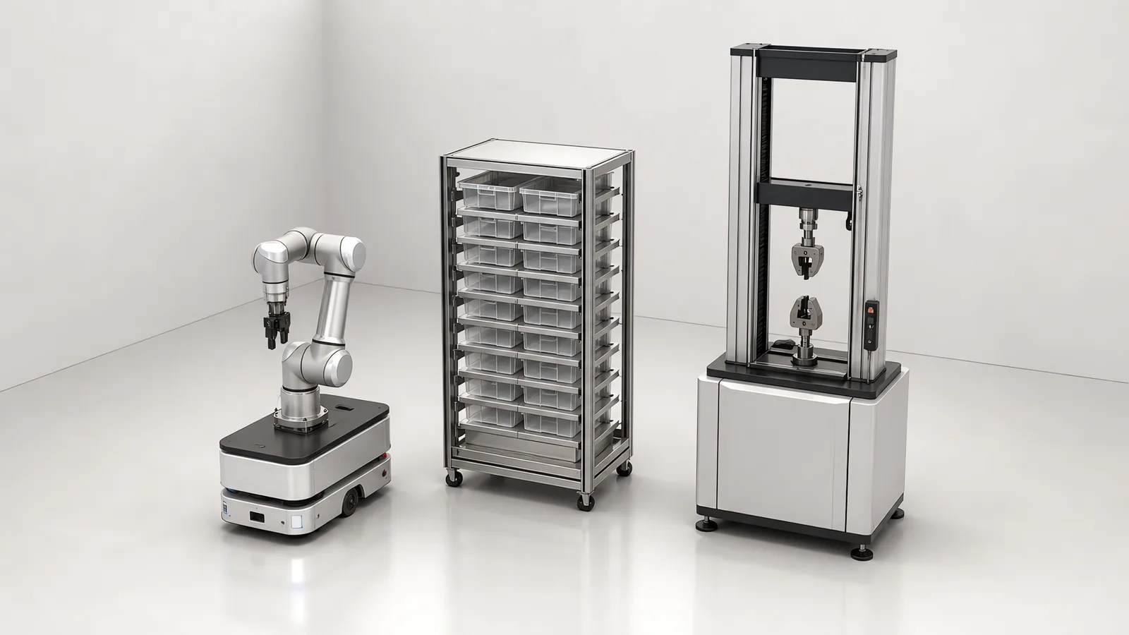
Motionwell Automation designs and builds laboratory automation systems for regulated QA and test labs in Singapore. The reference build is a QA Lab Transformation programme that has run for four consecutive years with the same customer, and is now being replicated for other manufacturers. The architecture stays the same each time: an autonomous mobile robot moves samples between storage and the benches, a collaborative robot loads and unloads the instruments, vision confirms what the robot is holding and where it is putting it, and a server-based scheduler decides what gets tested next. How that queue is built, prioritised and re-ordered when an instrument goes offline is on our laboratory automation scheduling page.
For the cross-station system described here, transport, handling, scheduling and traceability must work together. That does not require automating every task at once: a technician can retain a low-volume method while the system records its sample transitions. A single-instrument bottleneck may suit a smaller project. This page explains how the sample route, instrument interfaces and operating schedule set the scope and cost.
What Does a Laboratory Automation System Actually Do?
| Layer | What it does | What it replaces | Typical hardware |
|---|---|---|---|
| Transport | Moves samples between storage, benches, and return | Technicians walking trays across the lab | AMR, or AGV where the route is fixed |
| Handling | Loads and unloads instruments, opens fixtures, presents samples | Manual loading between test cycles | Collaborative robot, application tooling, gripper |
| Scheduling | Decides sample order, station assignment, priority overrides | A whiteboard and whoever is on shift | Server task scheduler with PLC execution |
| Traceability | Tracks sample state, names and files every result | Manual logbooks and hand-typed filenames | State machine in PLC, network file store |
The reason the four layers are listed separately is that they fail separately. A lab can have excellent instruments and still lose a day to a sample that was tested, passed, and then filed under the wrong name. Our delivered work in this space is documented on the laboratory and QA automation industry page, and the full system build is covered in the QA lab automation case study.
Why Did One QA Lab Keep Ordering for Four Years?
The scope grew, one phase at a time. The first covered a defined cluster of instruments and sample formats and had to prove one thing: that a sample could leave the rack, be tested, and come back with a result filed correctly, without a technician in the loop. Once that held under real production load, each following year added instrument types, sample formats, and floor coverage on the same control and data model.
That pattern is worth copying. It gives the lab a working system within one budget cycle, it exposes the awkward instruments early, and it means the second phase is integration work. The same rolling, site-by-site approach is how we deploy the electronic device history record (EDHR) system for a medical device OEM, where each site joins an existing data model.
How Do Samples Move Between Benches?
An autonomous mobile robot handles transport when routes change, when the floor is shared with people, and when new stations will be added later. The AMR navigates by its own map, takes missions from the scheduler over an API, and manages its own charging between jobs. A guided vehicle following a fixed route costs less and is the right buy where the route genuinely will not move, and the test for that is not the floor plan today but whether a bench can be added next year without re-laying guidance. Where it cannot, the tape or the reflectors get installed again at every lab reshuffle, and the saving on the vehicle goes back out on the second change.
Navigation accuracy and handoff accuracy are different design tasks. An AMR may park within about plus or minus 50 mm while the rack or fixture needs sub-millimetre placement. Physical docking, hand-eye vision and compliant tooling are ways to close that gap, selected for the station. On our laboratory system, vision measures the tray or fixture offset before the arm moves in, accommodating docking variance and station movement within the calibrated range.
That stack also fixes what an acceptance test is able to promise. ISO 9283 defines pose repeatability and pose accuracy as two different measurements with two different test methods, and it defines both for an arm on a fixed base under a stated load and stated conditions. The base is held still during that test because the base is not what is being measured. Mount the same arm on a mobile robot and the quantity the test held constant becomes the largest variable in the cell, which makes the arm’s repeatability figure a floor. A lab cell is therefore accepted on a measured handoff at the gripper, against the rack and the fixture it will actually work with, over a run long enough for the docking spread to show itself. Write that criterion into the specification. A cell accepted against an arm datasheet has been accepted against a test that was never run on the cell.
Storage is part of transport. A sample rack under system control has an addressable position for every slot, a record of what sits in each one, and a rule for what happens when a technician takes a sample by hand. Racks that are not under system control are a recurring source of the traceability gaps we are called in to fix.
How Does a Robot Tend a Laboratory Instrument?
The arm is the easy part. Collaborative robots with the reach and payload for lab work are commodity hardware now, so the arm is bought and the engineering goes into the tooling. A catalogue gripper is the right answer while the specimen offers a parallel pair of faces the jaws can take, the stroke covers every format in scope, and the force can be set low enough not to mark a test coupon. Past that line it becomes application tooling designed in-house, because a gripper that only works when the sample is presented perfectly has moved the problem into the rack, and the rack is the part of the cell nobody is watching on a night shift. The cell-level questions that decide whether a collaborative arm suits the work at all are on our cobot applications page. Where a lab has already standardised on a collaborative platform, we integrate onto the arm it owns.
The hard part is the instrument’s control interface, and it decides the project. Four cases come up:
- Native digital I/O. Start, busy, done, and error as discrete signals. A PLC drives this directly and it is the most reliable option available.
- Serial or Ethernet command set. The instrument accepts parameter setting, zero reset, start, and returns status and results. This gives the scheduler real feedback and is what we push for.
- Software API on the instrument PC. Workable, and it makes result capture clean, but it puts a PC in the critical path and its update policy becomes your problem.
- GUI only. No exposed interface. Options narrow to driving the vendor software or physically actuating the control, both of which need to be agreed with the instrument owner before anyone quotes.
This survey happens before design. An instrument list with make, model, firmware, and interface type is the single document that most changes a lab automation proposal.
Fixture and sample presentation is the other half of tending. Specimen geometry drives the tooling: a coupon, a syringe barrel, a plate, and a moulded part each need different gripping, different approach vectors, and different confirmation that the part actually seated. Vision does that confirmation, and it is specified as four separate checks: presence, orientation, the identifier on the specimen, and a post-load check that the part seated where the method needs it. A mechanical switch can report that something is in the fixture, which is not a report that the right specimen is in it the right way up, and in a lab the cost of that difference is a result filed against the wrong sample. How those cameras are specified, lit, and calibrated is covered in our machine vision inspection guide.
Labs are shared spaces, so safeguarding is designed in. Depending on the station that means guarding and interlocked doors, area laser scanners, or speed and separation monitoring where people and robots share the aisle. The reasoning behind each choice is in our note on collaborative robot safety standards, and every delivered cell goes through LVD and CE testing before shipment.
The handling constraints also differ by instrument. A tensile testing machine needs controlled specimen seating and a clear load path; a vibration testing machine adds a fixture and sensor arrangement that form part of the dynamic test. For helium leak testing, loading and valve sequencing must preserve the gas path and allow the measurement to recover before the next specimen.
A compression testing machine adds a platen-contact and specimen-removal problem to instrument tending. Define those conditions with the test method before designing the loader.
Does an Automated Loader Change the Test Result?
The instrument measures what it always measured. What automation changes is the handling around the measurement, and handling is where a test method keeps its conditions: how the specimen is held and at which point along its length, whether it seated fully in the fixture, which way up it arrived, how long it waited between leaving storage and starting, and what it sat in while it waited. A technician carries most of that in their hands and in their training, and none of it reaches the result file. A machine has to hold the same conditions explicitly. The useful consequence is that the test method, and never the instrument manual, is what the tooling gets designed against.
| What the method controls | How a technician held it | What the machine has to hold, and show it held |
|---|---|---|
| Grip position and orientation on the specimen | By hand, the way the bench was taught | Tooling that can present the specimen only one way, with vision confirming before the arm releases |
| Seating in the fixture | Felt it seat, reseated it when it did not | A seating check that produces a signal, with a defined action when the signal does not arrive |
| Waiting time before the test starts | Worked through the tray in whatever order suited the bench | A queue rule that respects whatever hold or conditioning time the method specifies |
| Where the specimen waits | On the bench, beside the instrument | A rack position under system control, recorded like any other state |
| Sequence of tests on one specimen | Remembered it | Enforced by the sample state machine and visible in the record |
This is why the method documents belong in the survey beside the instrument list. A method that says nothing about grip position is not permission to grip anywhere; it usually means the constraint lives with the technicians, and it has to be recovered from them and written down before tooling is designed. Where a method genuinely tolerates a range, that range is worth knowing as well, because it is what lets one gripper cover several specimen formats.
In a lab working under a quality system, this becomes the qualification argument. The protocols have to demonstrate that the cell holds the handling conditions the method sets, beyond the robot completes its cycle without stopping, and that distinction decides how much of the evidence is mechanical and how much is software. The structure that evidence gets written into is on our computer system validation page.
Flexure testing adds defined supports, spans and deflection measurement to the instrument workflow. bending-test fixture selection compares three- and four-point arrangements.
Hardness testing requires a named method, scale and specimen location. hardness method and handling links those decisions with instrument and automatic-handling checks.
Transient acceleration needs a defined pulse and loaded-fixture trial. mechanical shock test planning separates table input, product response and post-test function.
Board testing needs the property named explicitly. paperboard burst testing distinguishes Mullen material burst from finished-box compression and flexible-package leakage.
How Does the Scheduler Decide What Gets Tested Next?
A server-based task scheduler holds the work orders. It knows which samples are queued, which stations can run which test, which stations are busy or in fault, and which jobs carry priority. It issues missions to the AMR and jobs to the cell, and the PLC executes them with deterministic timing and reports back. Splitting it this way keeps the queue logic where it can be changed by software people and keeps motion and safety where they belong.
Three things separate a scheduler that survives contact with a real lab from one that does not:
- Priority override. A rush sample from a line stoppage must jump the queue without breaking the record of what was displaced.
- Station-aware routing. When one instrument goes down, the queue redistributes to compatible stations.
- Mixed manual and automatic operation. Technicians will keep running samples by hand at some benches. The scheduler has to accept that a sample left the system and came back, and never treat it as lost.
Total laboratory automation or connected islands?
Total laboratory automation, in the strict sense of one continuous automated path from sample receipt to filed result, is the right target for a lab with high volume, stable methods, and instruments that all expose control interfaces. Most manufacturing QA labs are not that lab. They have three or four high-volume tests worth automating end to end and a long tail of low-volume methods where a technician is faster and cheaper.
The practical target is a single scheduler and a single sample record covering the whole lab, with automated execution on the tests that earn it. That gives one queue, one audit trail, and a defined path to automate the next test later. Chasing full coverage on day one is how lab automation budgets get spent on the wrong benches.
How Is Every Sample Traced from Rack to Result?
Each sample is an object with an identifier and an explicit state: queued, in transit, loaded, in test, completed, failed, returned. Every transition is timestamped from one clock, so the record does not depend on which PC wrote it. Result files are named by rule from the sample identifier, method, and timestamp, then uploaded to the network location the quality system reads. No one types a filename.
Exception paths carry the same discipline, and they are what auditors look at. A retry is recorded as a retry. An operator intervention is recorded with the prompt that triggered it. A safe-hold is a state. Data integrity expectations in regulated labs come down to the ALCOA+ principles, attributable, legible, contemporaneous, original and accurate, and an automated lab is usually better at all of them than a manual one, provided the exception handling was designed.
Traceability is also where lab automation meets the rest of the quality system. For a medical device manufacturer, test results feed the device history record, which is why our EDHR work and our lab work share one data model instead of sitting in separate systems.
What Drives the Cost of a Laboratory Automation Project?
The instrument survey establishes the interfaces and handling work needed for a project estimate. The main cost drivers are:
| Cost driver | Why it moves the number |
|---|---|
| Number of distinct instrument types | Each interface is separate integration work, and it does not amortise |
| Instrument interface availability | Digital I/O or an Ethernet command set is cheap; GUI-only instruments cost real engineering |
| Sample format count | Each geometry may need its own tooling, fixture, and vision recipe |
| Transport topology | Fixed route with an AGV is one class; multi-floor or shared-aisle AMR routing is another |
| Safeguarding scope | Guarded stations, scanners, and certification testing scale with the number of cells |
| Data and validation scope | Network integration, controlled naming, and IQ/OQ/PQ documentation add engineering |
| Phasing | Building one system that grows costs less over four years than four systems that do not talk |
For context on the range: a benchtop liquid handler or a single automated tester from an instrument distributor is a catalogue purchase, and it sits far below a lab-wide transport, scheduling, and traceability system, because those are engineering projects. Both can be the correct decision. If one bench is the bottleneck, buy the instrument.
How Do You Automate a Lab That Cannot Stop Running?
Phasing is the whole answer, and it is a design constraint from day one.
- Workflow map and sample census: volumes per test, peak days, sample formats, current touch points, and where the time actually goes. Two weeks of measured data beats an estimate.
- Instrument interface survey: make, model, firmware, control interface, result output. This is the go or no-go gate.
- Concept and layout: route, station positions, rack capacity, safeguarding, and reach envelope checked against the real floor plan, including door widths, floor level changes, and lift access if the AMR crosses floors.
- Off-site build and factory acceptance: the cell is built and debugged at our facility against instrument surrogates, and the customer witnesses the acceptance test before anything ships.
- Installation in windows: rigging, power, network, and safeguarding go in during shutdowns or weekends. Nothing that touches the running workflow happens during a production shift.
- Shadow running: the system runs the workflow in parallel while technicians keep the manual path, and discrepancies are found here.
- Station-by-station acceptance and expansion: each station is accepted on its own, and the next phase begins from a working system.
Motionwell has run this pattern for four consecutive years in one lab, and delivered an AMR and cobot training cell to an institutional customer where staff learn the same workflow before it reaches their production lab. Our engineering, assembly, and commissioning happen in Singapore under an ISO 9001:2015 quality system, with bizSAFE Level 3 site practice.
Getting Started
The proposal is only as good as the input, so bring the following to the first review:
- An instrument list with make, model, and control interface for every machine in scope
- Sample formats with dimensions, weight, and how each is currently held or fixtured
- Volumes per test method, daily average and peak, plus the required turnaround for rush samples
- A lab floor plan with bench positions, aisle widths, door widths, and any floor level changes
- The data destination for results, and who owns the naming convention today
- Regulatory scope, including whether IQ/OQ/PQ documentation is required
Standards Used in Machine Design and Validation
These references inform the design, testing and documentation described on this page. Each row links to its primary source and records the edition checked.
| Standard | Current edition | What it means for your machine |
|---|---|---|
| ISO 9283: Manipulating industrial robots, performance criteria and related test methods | ISO 9283:1998 (second edition; reviewed and confirmed 2021, remains current) | Defines industrial robot pose accuracy, repeatability and their test methods. A positioning specification should identify the measured property, load, speed and test conditions so the quoted figure can be compared with the process requirement.Checked 8 Sep 2026 against ISO catalogue page iso.org/standard/22244.html (edition 2, published April 1998, confirmed 2021; ISO/TC 299) |
Frequently Asked Questions
What does a laboratory automation system include?
For a cross-station workflow, transport moves samples between storage and benches, handling loads and unloads instruments, scheduling assigns the next test, and traceability records sample state and results. Each layer can be automated or connected to a defined technician task. A single-bench project may only need instrument handling and a result interface; the sample route determines the scope.
Can robots operate the lab instruments we already own?
Usually, but the answer comes from a survey. Some instruments expose digital I/O, serial, or Ethernet control that a PLC can drive directly, including start, parameter set, and end-of-test handshake. Others only offer an operator GUI, in which case the software is driven through its own interface or the physical control is actuated. Instruments with no accessible interface and no exposed control are the ones we flag before quoting.
How long does a laboratory automation project take, and does the lab stop running?
The lab keeps running. Motionwell builds and debugs the cell at our Woodlands Link facility against instrument surrogates, so factory acceptance testing happens off your floor. Site work is scheduled into shutdown windows or weekends, and the system runs in parallel with the manual workflow until each station is accepted. Typical delivery for a first phase runs 16 to 24 weeks from concept approval, longer where validation documentation is in scope.