
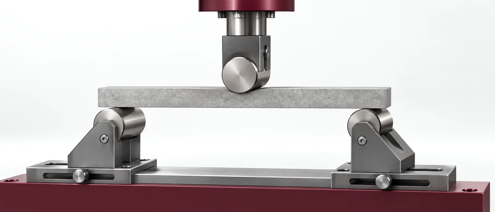
Conceptual equipment illustration.
A bending test machine applies load to a specimen supported in a defined arrangement and records its response. For a useful purchase specification, name the material test method, specimen geometry and required result before choosing the frame capacity. This is a materials-test instrument, not a press brake used to form production sheet metal.
In laboratory automation, the loading arrangement must remain reproducible when specimen handling becomes automatic. The existing QA laboratory case shows how instrument coordination and sample identity fit into an automated workflow.
Three Points and Four Points Are Different Tests
In a three-point arrangement, two supports carry the specimen and a loading nose acts between them. In a four-point arrangement, two loading noses act between the outer supports. The span and load positions change the bending conditions, so the fixtures are not interchangeable ways of obtaining the same result.
ZwickRoell’s flexure-test overview describes several configurations and material-specific methods. Use the chosen method to establish support geometry, loading-nose geometry and test sequence.
Record specimen width and thickness with the result. The equations for bending stress or strain depend on geometry and the applicable method; an unrecorded thickness change can affect a calculated result even when the measured force is unchanged.
Identify What Measures Deflection
Crosshead movement can include compliance in the frame and fixture as well as specimen deformation. If the requested result depends on local deflection, specify how that deflection is measured and where the measurement reference sits.
The purchase review should establish:
| Input | Configuration decision |
|---|---|
| Support span and specimen length | Fixture adjustment and seating space |
| Expected force and required low-force readings | Load-cell range and usable measurement interval |
| Required deflection | Stroke, clearance and deflection measurement |
| Temperature or conditioning | Chamber access and handling sequence |
| Result calculation | Measured channels, dimensions and method revision |
A shared universal frame may also handle tensile testing, but the grips and strain measurements differ. Compare the frame with its installed tooling and measurement channels.
Trial the Placement and Test Sequence
Load specimens repeatedly with the proposed handling method. Confirm that they sit on the supports without being bent or preloaded by the loader. Then compare the test records against equivalent manually positioned samples. Destructive tests need matched specimens; the same fractured specimen cannot provide an independent repeat.
Check that the software associates dimensions and method settings with the correct specimen. If the next test uses a different span, the fixture and calculation must change together.
A vibration-testing machine addresses repeated dynamic excitation, a different measurement task. Discuss the required bending result with Motionwell to define the instrument and automation interfaces together.