
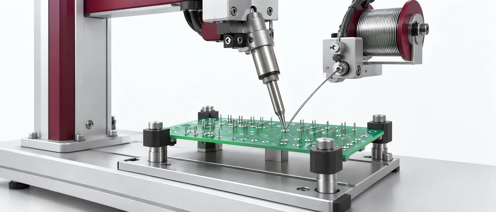
Conceptual equipment illustration.
A soldering robot repeats a defined soldering sequence on an electronics joint. Select the equipment through a joint trial that establishes heat transfer and material delivery. A consistently positioned tip can still produce an unacceptable joint if heat transfer or solder supply varies.
This guide concerns electronics soldering within an electronics production workflow, not arc welding or metal fabrication.
Prove the Thermal Sequence on the Joint
Joint material, copper area and component geometry influence the heat required. The tip shape and contact position determine how heat reaches that geometry. A controller’s temperature setting is not a direct measurement of every point in the joint.
Apollo Seiko’s L-CAT NEO-N description shows programmable solder-feed quantity, speed and temperature sequences. These settings support a qualified process; a list of settings alone is not product-quality evidence.
Trial the joint and component variation the cell will handle. Keep tip type, solder/flux specification and sequence with the trial. Compare results after a cold start and after sustained operation under the selected equipment’s procedure.
Check Access before Finalizing the Motion
The tip, feeder and fixture must reach the joint without colliding with nearby components. Check approach and withdrawal as well as the contact position. A taught point is not the complete motion envelope.
Board location and any fiducial correction must relate to the physical soldering tool. After tip replacement or fixture change, repeat the defined position and process checks.
The robot-integration scope covers cell coordination. The soldering process itself needs its specialist equipment and demonstrated joint recipe.
Separate What the Inspection Can Establish
A machine vision inspection can examine accessible joint appearance when the geometry and imaging allow it. Some internal or functional conditions need a different check. Use the product requirement to identify which conditions imaging can examine and which need separate tests.
Keep the required electrical/functional checks in the automated test equipment scope. Continuity, insulation and other characteristics answer different questions; choose the checks relevant to the assembled product.
Plan Consumables and Interrupted Cycles
Identify tip condition, cleaning and solder replenishment in the operating sequence. Establish how the system treats a board after a stopped soldering cycle, including which joints were completed and which need review.
Retain the board identity and process/test record. A restart should not repeat a joint blindly or skip one because the programme advanced before the interruption.
Discuss electronics handling and joint inspection with Motionwell to connect the selected process equipment with the surrounding automation and tests.