
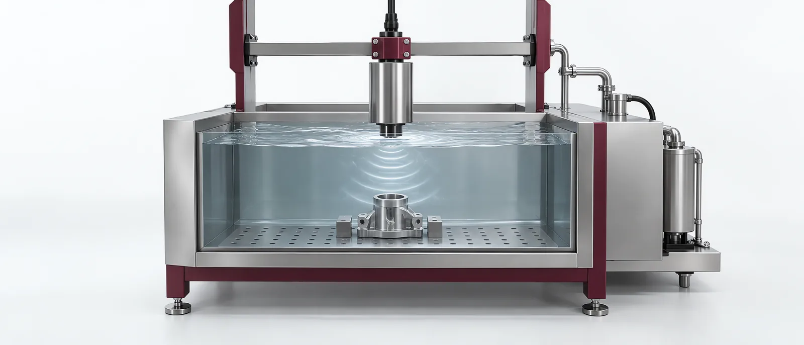
Conceptual equipment illustration.
An ultrasonic testing machine sends sound into a component and evaluates returned signals for the defined measurement or defect task. Select it from material, geometry and required coverage. Thickness gauging and flaw inspection can use related physical principles, but they do not have the same setup or acceptance criteria.
This is industrial non-destructive testing within an automated test workflow, not ultrasonic cleaning, joining or medical imaging.
Define the Sound Path
Identify the target material and geometry, expected discontinuity or thickness range and accessible probe surfaces. Specify the transducer, coupling method and reference configuration for that task.
Evident’s foundry-testing guidance discusses coupling, surface condition, sound velocity and material effects. These influence whether a usable return can be obtained and how a thickness result is interpreted.
A no-echo result is not automatically an acceptable component. It can also indicate an unsuitable sound path or unavailable coupling. Preserve that distinction in the equipment’s result states.
A Thickness Example Shows Why Calibration Matters
For a simplified normal-incidence pulse-echo thickness measurement, distance relates to sound velocity and round-trip travel time:
Thickness = velocity × time ÷ 2.
Assume 5,900 m/s and a corrected round-trip time of 10 microseconds. The illustrative thickness is 29.5 mm. The assumed velocity is not a universal material value, and this equation is not a complete flaw-sizing method.
Check calibration and reference pieces appropriate to the material and inspection. For another non-destructive method, our eddy-current testing guide explains a different physical route and its own material limitations.
Prove the Scan Covers the Intended Region
An automated scanner needs a known relationship between probe position and component position. Specify scan spacing, speed and the features that must remain covered, then test the actual path.
Save position with the relevant indication so that an operator can locate the result. A collection of traces without a component map can be difficult to use for disposition.
For aerospace and precision applications, the applicable product inspection method determines the acceptance evidence. Do not replace it with a generic automation demonstration.
Test Acquisition Failures Separately
Challenge coupling loss, interrupted scanning and an unavailable position signal. Establish whether the system stops, invalidates the test or requests a repeat. A partial scan should not silently become a complete pass.
The inline-measurement scope covers the broader association between instrument readings and moving parts. Discuss the ultrasonic inspection task with Motionwell to plan handling, scan coordination and records around the selected instrument.