
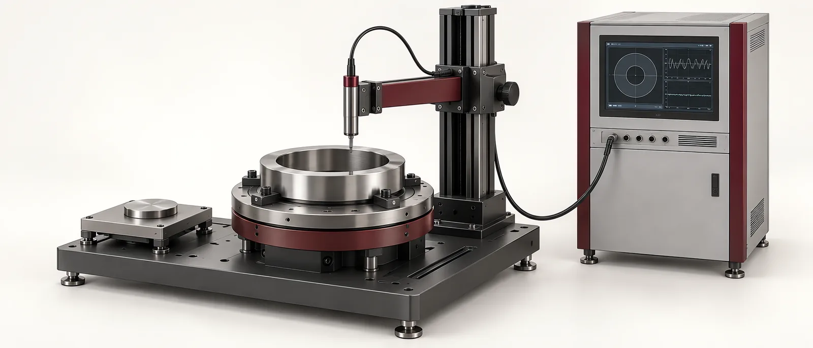
Conceptual equipment illustration.
Eddy current testing uses electromagnetic induction to examine electrically conductive parts. It can detect suitable surface or near-surface discontinuities and assess properties such as conductivity or coating thickness, depending on the instrument, probe and test setup. An automated station must preserve the conditions under which the defect signal was established.
Start with a defined inspection task: the material, the region to be scanned, the defect or property of interest and the acceptance basis. That definition is more useful than specifying an eddy-current instrument as a generic inspection device for every metal component.
Decide What the Signal Must Distinguish
Evident’s introduction to eddy current testing explains how an alternating magnetic field induces currents in a conductive part and how changes in the part alter the probe response. Material properties, geometry and the distance between probe and surface can influence that response as well as defects.
For aerospace and precision manufacturing, define the inspection region on the part drawing. A hole wall, a broad flat surface and a curved edge need different access and scan arrangements.
| Task definition | Fixture or process implication |
|---|---|
| Defect location and orientation | The probe must cover the relevant region in a useful direction |
| Material and condition | Reference samples must represent the inspection conditions |
| Surface shape and coating | Probe spacing and surface following need controlled treatment |
| Required coverage | The scan plan must identify starts, ends, overlaps and inaccessible areas |
| Decision and record | A result must be linked to a completed scan and a known part |
Penetration Is Not a Fixed Detection Depth
Frequency, electrical conductivity and magnetic permeability affect current penetration. Evident’s depth-of-penetration explanation describes the decay of current density with depth. That characteristic depth is not a promise that a particular crack will be found at that distance below the surface.
Select the probe and operating conditions against representative defects and material. Lowering frequency to obtain greater penetration also changes the inspection response; it does not simply extend an otherwise identical test deeper into the part.
This separates eddy-current work from surface-defect vision inspection, which depends on an optically visible feature and suitable lighting. The methods can provide complementary information when their individual tasks are defined.
Make the Scan Coverage Observable
A fixture should present the inspection region consistently and allow the probe to follow the intended path. For a rotating part, establish where the scan begins and how completion is confirmed. For a linear scan, define travel limits, position feedback and the treatment of starts and stops.
An array probe uses multiple coils and can collect position-related data across a wider area. Evident’s eddy current array tutorial describes the use of encoded position and C-scan presentation. This still requires a coverage plan; a larger probe does not remove the need to identify edges, transitions and regions it cannot reach.
Record a scan failure separately from a product failure. If the probe loses position or the motion stops early, the machine should not convert incomplete coverage into an accepted part.
Use Reference Samples to Control the Inspection
Define the reference sample’s material, geometry and relevant features, then record the instrument settings and probe used with it. Include the condition of the probe and its mounting in the setup check.
A useful acceptance exercise runs the agreed references through the complete automated path, then repeats the setup after an ordinary fixture change. Compare the resulting signals and coverage records. The objective is to show that the automated handling preserves the inspection method, not merely that the axis can move through its programme.
Where the cell also checks dimensions, keep the result channels distinct. The inline dimensional measurement page explains the separate measurement-chain questions around locating and gauging a part.
Connect the Instrument to the Cell Record
For each inspected unit, associate its identity with the method, scan completion state and acceptance result. Preserve the additional trace or scan data required by the inspection plan. Include a defined response to a missing instrument result and to a failed reference check.
These interfaces belong in the automated test equipment architecture alongside loading, sorting and data export.
Planning an automated inspection operation? Tell us about the part and inspection task. We can discuss presentation, probe motion and the interfaces around the selected instrument.