
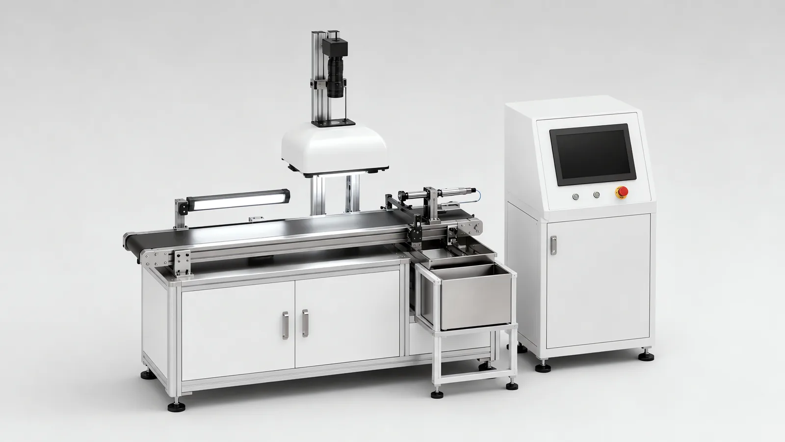
Motionwell builds surface defect inspection systems in Singapore for scratches, contamination, flash and other visible defects on production parts. The first inputs are defect definitions, limit samples and the surfaces to inspect. Lighting, part presentation and camera views are then tested together so acceptable variation can be distinguished from a reject condition. Our panel assembly work provides related experience in controlled lighting, vision recipes and station-result tracking.
The short version comes first. A dimensional station inherits its pass criterion from a drawing you and your customer already agreed on. A surface station has no drawing. The criterion lives in whoever does the grading today, it has not had to survive being written down, and it cannot be built into a machine until it is. That is why surface work is harder than measurement, why the first deliverable is a written defect specification and a set of physical limit samples, and why the only useful answer to “can vision catch this” is to image your bad parts and show you what comes back.
This page is about judging appearance: scratches, dents, contamination, print quality and missing or wrong features. The architecture questions shared by every camera station, smart camera versus PC-based, optics and working distance, trigger and PLC handshake, are on our machine vision inspection capability page, and the resolution arithmetic is in the vision inspection guide for electronics. Measuring a feature against a tolerance is a different problem, covered on our inline dimensional measurement page.
Why Is Surface Defect Inspection Harder Than Dimensional Measurement?
Both stations use a camera. The difference is not optical, it is where the pass criterion comes from.
| Dimensional check | Surface defect check | |
|---|---|---|
| Where the criterion comes from | The drawing, already agreed with your customer | A judgement held by whoever grades the parts today |
| What the output is | A number with a tolerance around it | A verdict, with no natural units behind it |
| What proves the station | A calibrated artefact and a gauge repeatability study | Graded parts, and agreement between the people who graded them |
| What a disagreement means | One instrument is out of calibration | The specification was never written tightly enough to disagree about |
| What you need to set it up | The part and the drawing | Real defective parts in every class, including marginal ones |
| How it drifts | Thermal, mechanical, calibration interval | Lighting ageing, optics contamination, a supplier changing surface finish |
| What failure looks like | A measurement that reads slightly wrong | A reject rate nobody can explain, and a station that gets switched off |
Two consequences shape the project. First, a surface station cannot be specified from a part drawing. On medical device builds we deliver gauge repeatability and reproducibility studies, and that method works because a measurement has a reference value to spread around. A verdict on a scratch has none. The equivalent evidence is agreement: hand the same graded parts to two experienced people, twice, and see whether the four verdicts match. Where they do not, the specification needs work.
Second, the defect class decides the hardware. A scratch, a smear of contamination and a missing gasket are three optical problems wanting three lighting geometries, and a station asked to catch all three is usually several exposures.
What Has to Be Written Down Before a Defect Class Can Be Detected?
This is the deliverable that unblocks everything else, and it belongs on paper before hardware is priced. Vision defect classification is only as good as the class list it is given, so a workable defect specification states the following, per class.
- The classes, named separately: scratch, dent, contamination, print defect, missing or wrong feature. They get grouped in conversation and have to be separated on the machine, because each wants different illumination and earns its own threshold.
- The size limit: the smallest instance that must be caught and the largest that is acceptable. Both numbers, because a station told only what to catch has no definition of a good part.
- The zone. A mark on a face the user sees is not the same defect as the identical mark on an internal boss. Set a limit per zone, or the tightest requirement anywhere silently becomes the requirement everywhere.
- The accumulation rule: whether three acceptable marks inside one area are still acceptable. This rule is often missing, and it decides whether the reject rate is stable.
- Cosmetic or functional. A cosmetic reject can often be reworked or downgraded; a functional one cannot. The two do not belong in the same bin, and the distinction has to exist before the reject handling is designed.
- What happens to a reject: scrap, rework, clean and re-present, or hold for review. The mechanical design of the station follows from this answer.
This rarely exists in writing before a project starts, and that is not carelessness. The criterion has not needed to exist in writing, because a person applied it, and a person applies context that a threshold cannot. Writing it down is real work, and it pays off beyond the machine: it is the moment your own graders find out they disagree.
The practical instrument is a limit sample set, physical parts kept as the reference, one at the acceptable limit for each class and one just beyond it, signed off by the quality function. Photographs alone are not enough, because the question is how the part behaves under light. Label them, and store them where a helpful operator cannot clean them.
Where Do the Defective Samples Come From, and How Many Do You Need?
Surface projects meet the same wall: the parts needed to build the inspection are the ones your process is designed not to make. Our standing request for a feasibility study is 5 to 10 good parts and 5 to 10 with each defect type you care about, plus your current inspection criteria, the line speed and how the part is presented today. That is easy to write and hard to fill, for four reasons.
Rare classes do not arrive on schedule. A class that appears a few times a year will not turn up during a project, so collection has to start before the order, which means agreeing now that the line stops throwing them away.
The marginal parts decide the operating point, and they are the ones a plant usually has not kept. Obvious defects and clean parts sit far apart in any score distribution and settle almost nothing. The operating point is decided by the population in the middle, and those are the parts that got passed, shipped or quietly rescrapped.
Engineered defects are not the same object. A scratch cut with a blade or a dent pressed on a bench is worth making when nothing else exists, but it lacks the edge profile, depth and optical behaviour of the real thing, so a station tuned on manufactured defects gets rechecked on real ones before sign-off.
Samples change while you hold them. Contamination dries, wipes off or migrates, and bright metal tarnishes. Image the set under the study lighting when it arrives, so there is a record of what was agreed.
Hold part of the set back, so the finished station can be checked against parts it has never seen. And decide who owns the library, because it only gets more valuable as classes are added, and it is what lets the station be re-tuned in year three without starting again.
Which Lighting Reveals Which Kind of Surface Defect?
Lighting decides whether a surface station works far more than the camera does, for a reason specific to appearance work. A dimensional feature is a strong edge that most reasonable illumination will show. A defect is a small deviation on an otherwise uniform surface, so the whole job of the lighting is to make that deviation the brightest or darkest thing in the frame. Get it wrong and no sensor recovers it, because the information was never in the image.
The organising idea is whether specularly reflected light reaches the lens. In bright field the surface reflects into the camera and reads bright, so anything that scatters or absorbs reads dark against it. In dark field the light arrives at a grazing angle and the flat surface reflects it away, so the frame is dark and only height changes scatter light back. Either can be the primary geometry, and a class the first cannot show needs a second exposure.
| Defect class | What the light has to do | Geometry that does it | What that geometry also does |
|---|---|---|---|
| Fine scratch, scuff, drag mark | Turn a height change into a bright line on a dark field | Low-angle dark field ring, grazing | Lights every harmless machining mark, mould line and grain feature just as brightly |
| Dent, emboss, deformation | Cast a shadow at the edge of a broad height change | Directional bar at a controlled angle | Direction-dependent: a feature parallel to the light can vanish, so two azimuths are often needed |
| Contamination, fibre, residue, stain | Show a reflectance or colour difference where there is no height difference | Diffuse dome, bright field | Cannot separate a mark on the surface from one under a transparent layer |
| Print, code or label quality | Even illumination with no specular hotspot on a glossy or curved face | Dome, or coaxial on flat specular material | Contrast comes from ink against substrate, so a fading mark still reads as present |
| Missing, wrong or misplaced feature | Make presence a hard binary difference | Backlight silhouette, or bright field where reflectance differs | Unforgiving about seating: a part that rocks in the nest reads as missing |
| Flash, burr or moulding artefact at an edge | Break the outline while still showing the face | Backlight for the profile plus grazing light on the face | Two lights and usually two exposures, rarely one setup |
The choice we make most often shows the trade. On a multi-station rotary assembly machine handling translucent polycarbonate and polished stainless parts, we would put dome lighting on the vision stations, because both materials throw specular highlights under directional light, and a highlight sitting on a contour edge is indistinguishable from a real dimensional deviation to the measurement algorithm. Dome also lets scratches, contamination and flash read consistently regardless of their angular orientation on the part, which matters where the part arrives in a nest. The cost is real: dome heads are bulky, occupy the vertical space directly above the station and constrain how a gripper approaches it, and on a dial the light head can end up setting the nest pitch. That decision was taken for the same reason on the delivered vision-guided sensor panel assembly line, where connector pins and solder joints glare under directional light. Where a vision gate belongs on a dial, and how it is given the dwell it needs, is on our page on how we design multi-station rotary assembly machines.
Two environmental points hit appearance stations harder than presence checks. The defect signal is a small fraction of total scene brightness, so factory light through a roller shutter moves the reject rate, and the fix is a shroud. And on cleanroom builds, cameras and their lighting sit behind a sealed window because the hardware runs warm and has its own airflow. A window is another specular surface in the optical path, and dark field tolerates it far less than a code read does, so its angle, coating and cleaning schedule belong in the optical design, as covered in our cleanroom automation design guide.
Lens selection must preserve the defect evidence across the permitted view and part positions. The machine vision lens guide sets out a practical trial using marginal samples, height variation and actual exposure conditions.
A scratch and normal surface texture need distinguishable images. surface-inspection lighting trials explains how to compare low-angle, diffuse and other arrangements on samples.
What Makes Specular and Curved Surfaces the Hard Case?
A shiny surface does not show you itself, it shows an image of whatever is around it, and a curved one presents only a narrow band at the right angle to any fixed light. These conditions decide whether a defect can be lit at all, so they are worth checking before anything else.
| Surface condition | What goes wrong | What usually works |
|---|---|---|
| Mirror-finish flat metal | The camera images the room, the fixture and the operator | Coaxial on-axis light so the surface returns bright and only defects break the field, plus shrouding what would be reflected |
| Polished or translucent plastic | Specular highlights land on contour edges and read as deviations | Diffuse dome, the choice we would make for polycarbonate or polished stainless medical parts |
| Cylindrical, domed or contoured | Only part of the surface is at a usable angle at any instant | Rotate the part under a fixed camera and inspect in several angular positions |
| Brushed, grained or textured finish | The grain scatters light the same way a scratch does | Light it against the grain and separate by direction: the grain is aligned, a defect usually is not |
| Transparent or clear-coated | The defect may sit on the surface, under the coating, or on the far wall | Separate layers by focal plane or lighting angle, and decide at specification stage which is a reject |
| Anything that cannot be presented identically | The threshold moves with the part | Fix the fixture before touching the recipe; a rocking part sets a detection floor no tuning beats |
Inspection of a cylindrical part may require several indexed views, so rotation and exposure belong in the cycle-time budget. Stations on a common rotary dial share the same dwell. A servo indexer adjusts that shared timing; extra inspection capacity comes from parallel cameras, overlapping suitable operations or moving a long inspection to a decoupled station. The required views and processing time determine which arrangement fits the target rate.
Rule-Based or Trained: What Are You Actually Trading?
The dividing line is short: rule-based tools work when you can describe the defect, and a trained classifier earns its place when you can only show examples, such as a scratch that matters against a scratch that does not. The rest of the decision is about what you own afterwards.
| Rule-based tools | Trained classifier | |
|---|---|---|
| Fits when | The defect can be expressed as a threshold on area, contrast, length or position | The class is visually variable and rule-based logic produces false rejects |
| You supply | A written criterion and enough parts to set the thresholds | A labelled image library covering every class, including marginal cases |
| Buy-off argument | The threshold is visible, so a disputed part can be re-run and explained | Performance against a held-back set, a statistical argument |
| A new class appears | Add a tool and a threshold, retest that tool | Collect and label images, retrain, revalidate the model |
| The process changes | The affected tools are re-tuned | The model may need retraining even where the defect did not change |
| Auditability | High: the decision rule reads off the configuration | Lower: the decision sits in learned weights, so the evidence is test results |
| On a regulated line | A configured vendor toolset is normally the lighter software category | Retraining changes what makes the decision, so it is a change control event |
| Who maintains it | A plant technician in the vendor GUI | Whoever owns the image library and the retraining procedure |
Where a classifier is genuinely the right answer, the question to settle first is whose classifier it is: a trained tool that ships as an option inside a vision vendor’s own toolset and is configured through its interface, or a model written and hosted as bespoke software. On the line they behave alike. In an audit they do not, and the bespoke one carries the heavier evidence burden. The inspection we deliver is rule-based by default, and on the sensor panel line that means pattern matching and edge detection for presence and orientation, with the deciding threshold readable off the configuration by whoever has to defend a rejected part. On a rotary assembly machine we would build an appearance check the same way, edge and contour tools under dome lighting with a per-class OK/NG result driving the sorting at unload.
Two things are worth saying plainly. A trained classifier does not solve the sample problem, it enlarges it: a model needs more labelled examples than a threshold does, and the labels have to be as consistent as the criterion you have not written yet. And on a regulated line, a configured vision package and a bespoke inspection script sit in different GAMP 5 categories, the second carrying the heavier evidence burden, as set out on our computer system validation page. Neither makes a classifier wrong. It is a decision with a maintenance commitment attached.
For a learned surface-defect method, review AI defect-validation planning. Keep acceptable variation and critical missed defects visible instead of reporting only combined accuracy.
How Is the Operating Point Set, and Why Does the False Reject Rate Decide Whether the Station Survives?
Every inspection tool produces a score, and a threshold turns it into a verdict. Where that threshold sits is a commercial decision about which error you can afford, and the general method for setting it is on our machine vision inspection page. Three things are specific to appearance work.
Set an operating point per class. A contamination class with heavy score overlap and a missing-feature class with almost none do not belong under one threshold, and where the station reports only a composite verdict, nobody can tell which class is driving the reject rate. Keep the per-class result even where the reject action is identical.
The false reject rate is what gets a station switched off. An escape is discovered later, somewhere else, by someone else. A false reject is felt on the line this shift, by the people standing next to the machine. The sequence that follows is predictable: reject rate climbs, production falls behind, limits get widened until everything passes, and the station survives as an expensive indicator lamp. An inspection the operators trust is worth more than one that is stricter on paper, and that is an engineering constraint.
Numbers only mean something against a named sample set. An escape or false reject rate quoted without saying which parts it was measured on cannot be tested at acceptance. Ask for the rate to be stated against a named set with the held-back parts inside it, so the figure can be re-run at acceptance.
After handover, trend reject rate by class and by shift. A rising rate on a stable process points at the physical layer: lighting output falling with age, dust on the lens or cleanroom window, a fixture wearing, or a threshold someone moved without recording it. Counting every part is also what makes an escape rate knowable, as we argue in our note on medical device automation trends.
What Happens to a Rejected Part, and What Gets Recorded?
A verdict that nothing acts on is not an inspection, and appearance stations carry one requirement the general case does not: segregation by class.
A scratch reject, a contamination reject and a missing-feature reject usually have different destinations. One is reworked or downgraded, one is cleaned and re-presented, one goes back to assembly, and only some are scrap. Where that matters we use a robot pick-off, because a robot can place parts into separate destinations by defect class, dropping nothing into one bin. Where a single bin is enough, the usual pattern is a pneumatic pusher downstream of the vision station diverting failures into a quarantine bin. We synchronize the reject device with the inspection result through the control sequence, tracking each part from the inspection point to its assigned exit. The reject device needs a sensor proving the part left the line, because a stuck pusher passes failed parts downstream while the log still records a rejection.
Image logging is not optional here, for a specific reason. A dimensional decision can be re-created by re-measuring the part. An appearance decision cannot: by the time anyone asks, the part has been handled, wiped, reworked or scrapped, and the surface that was judged no longer exists in that state. The image is usually the only evidence of the decision. A reject handler should log each rejection with the serial number, the reason and the inspection image behind it, so that quality review and SPC analysis have evidence to work from, and where the line keeps an electronic device history record, such as the one we built for a medical device manufacturer, that log is where the record belongs.
Two decisions follow. Whether to archive every image or only rejects is a storage question for design stage, and it is one of the arguments that pushes a station from a smart camera to a PC-based architecture. And where it forms part of a batch record, 21 CFR Part 11 applies: audit trail, controlled retention and access control get designed in.
How Is the Decision Proven on Your Parts Before You Buy?
Only real parts settle the lighting question, so this sequence starts before a quotation.
Send parts with your inspection criteria, line speed, presentation method, PLC platform and reject sequence. We compare lighting configurations on those samples and record the detection result by defect class. The trial provides sample images, a recommended configuration, any additional sensing needed and a budget range for the station.
If the project proceeds, the acceptance evidence worth writing into the order is a run against the graded set, never a demonstration on good parts: limit samples, marginal parts and the held-back set, presented and re-presented so the fixture is inside the test, because how the part seats is part of the measurement. Factory acceptance testing happens at Woodlands Link with the buyer present. That is the practical argument for a Singapore buyer working with a Singapore builder here, because the adjustments that decide whether an appearance inspection holds are lighting and fixture details found on your own parts.
Which Inspection Method Matches the Defect?
Visible surface variation. Establish a repeatable signature across acceptable, marginal and defective samples. Trials compare lighting direction, wavelength, views and fixture repeatability before setting the classification thresholds.
Internal defects and leaks. Subsurface porosity, voids, delamination and covered cracks call for a suitable X-ray, ultrasonic or CT method. Pressure-decay or tracer-gas testing addresses leak requirements. A production sequence can combine these checks with camera inspection and route the results under one part identity.
Properties beyond appearance. Shot peening needs separate process checks: Almen strips and the saturation procedure establish peening intensity, while coverage is evaluated using the specified surface-inspection method and exposure plan. Motionwell’s turbine-blade equipment coordinates nozzle motion and process parameters for those checks. The application is described on our aerospace and precision automation page.
Defects linked to a process step. Use inspection results to identify the handling step, tool or transfer generating a defect. Process correction and detection can then share measurable targets for yield and escape rate.
Standard or custom inspection hardware. Compare a proven inspection unit with a custom station against the same parts, rate, defect classes and record requirements. Integration covers presentation, reject handling and the link to your line controls.
For conductive components, eddy current testing can address suitable surface or near-surface discontinuities using an electromagnetic response. Establish its reference samples and probe path separately from the lighting and image thresholds used by the vision station.
What Drives the Cost and Lead Time of a Surface Inspection Station?
Surface inspection cost follows the defect size, number of views, presentation method, cycle time and record-retention requirements. The decisions below explain why two similar-looking stations can require different hardware and engineering effort.
| Cost driver | Why it moves the number |
|---|---|
| Number of distinct defect classes | Each can want its own lighting geometry, tool set and threshold |
| Whether a written criterion exists | A signed-off limit sample set shortens the project; writing one is real engineering time |
| Sample availability | Rare classes turn collection into the critical path, ahead of hardware lead time |
| Surface finish and geometry | Specular, curved and grained surfaces drive views and exposures per part, and those drive cycle time |
| Part presentation | An existing repeatable nest is cheap; rebuilding presentation is a mechanical project |
| Archive scope | Rejects only, or a full-resolution image of every part, which changes architecture and storage |
| Rule-based or trained | A classifier adds a library, a labelling effort and a retraining procedure you keep |
| Reject segregation | One quarantine bin, or sorted destinations by defect class with a robot placing them |
| Validation scope | Part 11 records, audit trail and qualification protocols are a documentation project alongside the build |
Lead time runs 16 to 24 weeks from concept approval to factory acceptance testing on a standard build, and 24 to 32 weeks where cleanroom compatibility or full GMP validation applies. The item that sits outside that schedule is sample collection, which is why it should start at the enquiry. How a build of this shape is scoped from concept to commissioning is in our guide to special purpose machine design.
Frequently Asked Questions
Why can you not quote a surface defect inspection system from a description of the defect?
Because a defect class has to be defined before anything can be built to detect it, and a description is not yet a definition. 'Scratches' becomes a specification only when it states the smallest scratch that must be caught, the largest that is acceptable, which surface zones the limit applies to, and whether two acceptable marks close together are a reject. Until that is written down, two experienced graders in your own plant can disagree on the same part, and a vision station is no more consistent than the criterion it copies. The practical way to settle it is against physical limit samples, which is where a feasibility study on your own parts starts.
How many defective parts do you need for a surface inspection feasibility study?
Real ones from every class you need caught, plus the borderline ones. Our standing request for a feasibility study is 5 to 10 good parts and 5 to 10 with each defect type you care about. Clean good parts and obvious defects are the easy half of the set and settle almost nothing. The marginal parts are what set the operating point, and they are the ones a plant usually cannot produce, because an operator scrapped them months ago. Where a defect class is rare, start collecting before the project starts, and keep some back so the finished station can be checked against parts it has never seen.
Should a surface defect station use rule-based tools or a trained classifier?
Use rule-based tools when you can describe the defect, and a trained classifier when you can only show examples of it. A rule-based station is auditable: the threshold on a blob area or a contrast score can be read off, explained to your customer and re-tested on demand. A trained classifier buys you defect classes that resist description, and costs you a defect image library you have to own, keep and extend, plus a revalidation story every time the model is retrained. On a validated line that is a change control and software categorisation question before it is a technical one.