
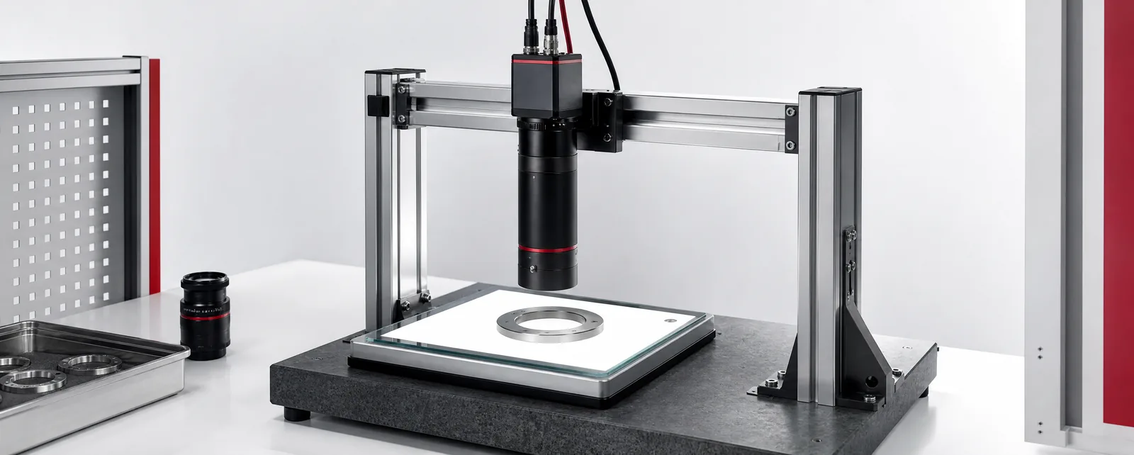
Conceptual equipment illustration.
Select a machine vision lens from the feature you need to inspect, the field of view and the space available between the camera and the part. Match it to the sensor, lighting and presentation method, then test the assembled optical setup. Focal length alone does not tell you whether a defect will be visible or a measurement will meet its tolerance.
The lens decision belongs inside the machine vision inspection system design. It determines what reaches the image before software makes a decision.
Fix the View and Working Distance Together
Define the area that must be visible, including position variation at the inspection point. A part that just fits a nominal image can leave the frame when its nest, conveyor position or orientation changes.
Edmund Optics’ basic lens selection guide identifies working distance, field of view and resolution as fundamental selection constraints. With a chosen camera, use those constraints to shortlist lenses. Confirm the actual sensor coverage, mount and space needed for lighting before fixing the bracket layout.
Write the working distance from the reference point stated in the lens documentation. Allow for the longest part variant, mounting adjustment and access for cleaning. A nominally suitable lens can become impractical if it occupies the space needed by a gripper or inspection light.
Calculate Sampling, Then Test Visibility
Consider an illustrative camera with 2,448 horizontal pixels covering an 80 mm horizontal field of view:
Object-space sampling = 80 mm ÷ 2,448 pixels ≈ 0.0327 mm per pixel.
A 0.10 mm feature spans approximately 3.1 pixels in that direction. This describes image sampling; it is not a guaranteed detection limit or measurement accuracy. The feature still needs enough contrast, suitable focus and an exposure that preserves its appearance.
Use the calculation to compare configurations. If the same camera covers 160 mm, the sampling becomes approximately 0.0654 mm per pixel and the feature spans about 1.5 pixels. That change exposes the trade-off between covering the whole part and recording its smallest relevant detail.
For boards and panels, the electronics vision inspection guide connects that trade-off to the feature and inspection task. Do not approve a lens merely because the camera’s megapixel count looks large.
When Is a Telecentric Lens Worth Testing?
For dimensional gauging, changes in part height can change apparent size with a conventional perspective lens. An object-space telecentric lens reduces this perspective effect within its specified operating range. Edmund Optics explains the magnification behaviour and depth-of-field considerations.
Telecentricity does not remove every measurement error or provide unlimited depth of field. Check the required view, permitted height variation and usable image contrast with the actual setup. For a ring diameter, compare results at the centre and edges of the view, then repeat at the allowed seating heights.
The broader inline dimensional measurement scope includes the datum, calibration and capability trial. Those decisions determine whether the completed gauge meets the drawing, beyond the lens’s optical specification.
Use a Trial That Can Reject a Poor Lens Choice
Agree the inspection task before the demonstration. An attractive image of one good part does not show whether the system distinguishes an acceptable surface from a reject condition.
Build the trial around the variation the station will see:
| Trial condition | Question to answer |
|---|---|
| Part at centre and outer positions | Does the relevant feature remain usable across the view? |
| Minimum and maximum permitted height | Does focus or apparent size alter the decision? |
| Actual line motion and exposure | Does movement hide the feature? |
| Good, marginal and defective samples | Can the decision separate the defined classes? |
| Changed ambient light and part finish | Does the lighting arrangement preserve the evidence? |
For scratches and contamination, use the surface defect inspection approach to define the defect classes and sample set. The optical trial should reveal those defects, not substitute a convenient printed target for the real surface.
What to Compare in the Quotation
Compare the camera, lens and lighting as one proposed configuration. Ask for the resulting view and working distance, adjustment range, sample-trial images and the method used to verify the decision. Record the mounting arrangement and how settings are secured after commissioning.
Keep a reference image set and the final configuration with the handover. That gives maintenance a practical way to check a replacement lens or disturbed bracket against the accepted setup.
Need a lens and lighting arrangement for an inspection station? Discuss the feature and available space with Motionwell.