
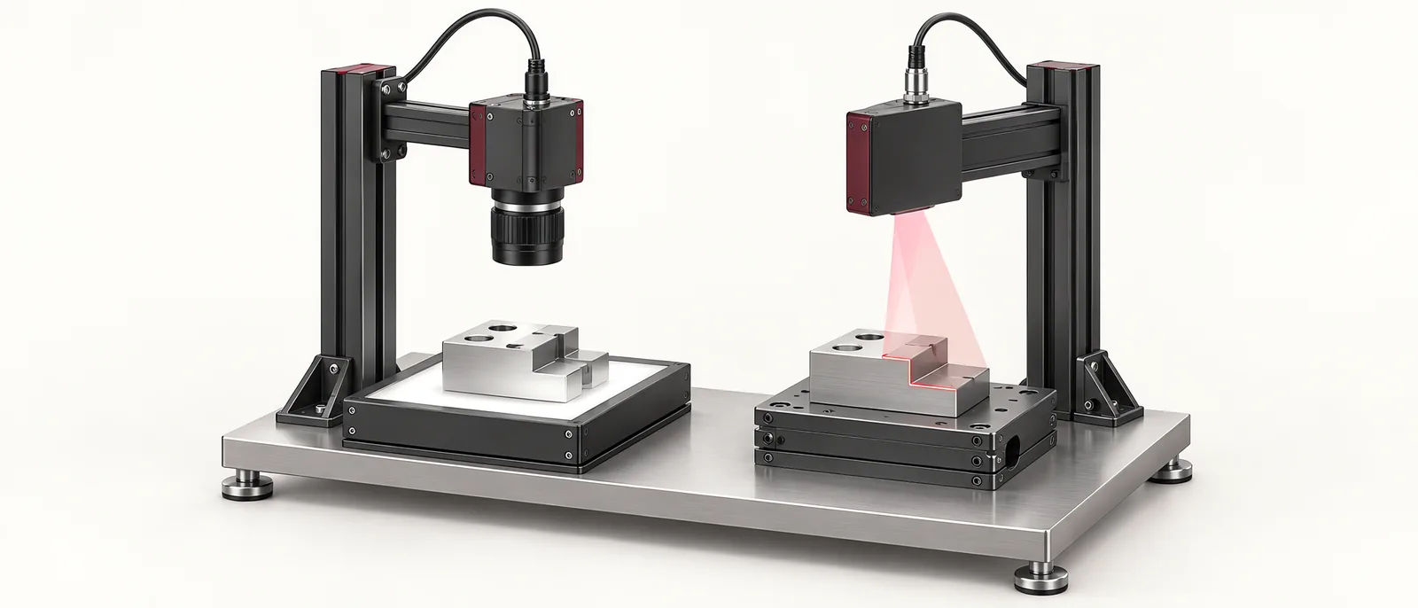
Conceptual equipment illustration.
The choice between 2D vs 3D machine vision systems starts with the measurement. A conventional 2D image records appearance in the image plane. A 3D system adds depth or height information through its sensing method. Use 3D when the required distinction depends on that additional geometry, not simply because it sounds more capable.
A label-presence check may be solved with a clear 2D view. Measuring a raised feature relative to a surrounding surface requires a suitable geometrical measurement arrangement.
Name the Quantity Before the Camera
| Inspection question | Starting approach | Condition to verify |
|---|---|---|
| Is the correct label present? | 2D appearance or identity check | Artwork visible under normal presentation |
| Is a hole in the correct position? | Calibrated 2D geometry where suitable | Stable plane, optics and reference features |
| Is a feature above the permitted height? | Depth or profile measurement | Reference surface and feature both measurable |
| Is an adhesive bead continuous? | 2D or 3D according to the defect | Appearance may show a gap; height or volume needs geometrical evidence |
| Where can a robot grip an uneven pile? | A suitable pose-estimation method, often using depth | Visible grasp geometry and occlusion handling |
KEYENCE’s 2D and 3D comparison describes the additional surface geometry available from 3D sensing. A 2D side view can still measure a visible projected height; the issue is whether the chosen view actually provides the required quantity.
Do Not Confuse Depth With Accuracy
More dimensions do not automatically mean a more accurate measurement. Field of view, optical geometry, calibration, surface response and presentation all affect the result. Compare the measurement uncertainty and repeatability required for the specific feature.
The in-line dimensional measurement scope should define datums, dimensions and acceptance limits before a sensor is selected. An attractive height map is not, by itself, a verified measurement system.
Match Acquisition to Motion and Surface
A scanning arrangement builds information as the part or sensor moves. Its geometry depends on the relationship between that motion and acquisition. A snapshot arrangement captures an area through its particular sensing method. Both need a clear view of the relevant surfaces.
Trial reflective, dark, translucent or low-contrast examples from the actual product range. Inspect missing or unreliable data as well as successful measurements. Do not let the software silently turn an unobserved region into a good part.
The part feeding and presentation design can provide stable height, orientation and spacing. Reducing uncontrolled presentation may simplify either a 2D or a 3D inspection.
Separate Imaging From the Processing Platform
The decision between 2D and 3D describes the information being acquired. The decision between a smart camera and PC-based processing describes where and how it is processed. These choices interact, but they are not the same comparison.
Our machine vision inspection guide covers the wider lighting, acquisition and integration process. Select the computing arrangement after confirming the required images and processing workload.
Run a Matched Sample Trial
Use the same acceptable and defective parts when comparing approaches. Include the minimum defect, difficult surfaces, permitted orientations and production motion. Record detection failures, false rejects and invalid measurements separately.
For dimensional tasks, compare results with an appropriate independent reference. For classification tasks, retain the agreed expected result for each sample. The preferred system is the one that demonstrates the required distinction reliably within the machine cycle.
Discuss your inspection task with Motionwell and review our machine vision integration scope.