
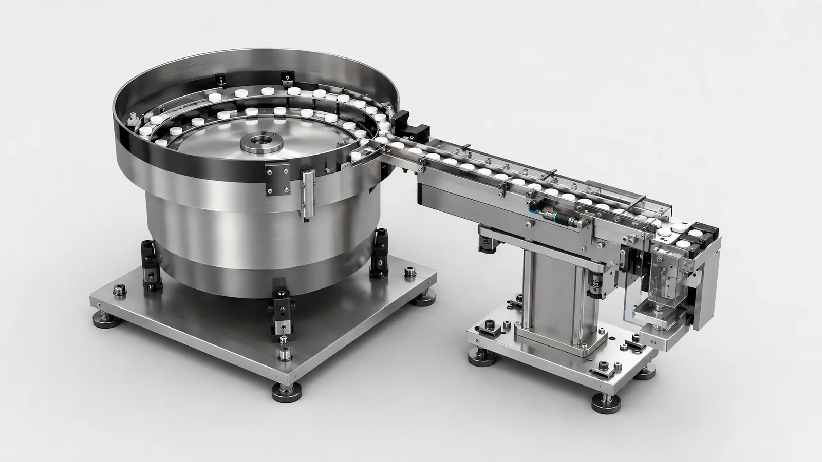
Motionwell Automation designs and builds part feeding systems in Singapore to present each component in a repeatable position and orientation at the required rate. The choices include bowl feeders and escapements, starwheel indexing, trays, magazines and vision-guided presentation. We select the mechanism from part samples, surface sensitivity, product mix and replenishment access.
Delivered work includes escapement stations, bowl feeder retooling with starwheel indexing, tray-fed filling and vision-guided SCARA panel assembly. For a rotary assembly machine, we design the feeder, chute and nest together; the layout decisions are explained in multi-station rotary assembly design.
Feeding is designed and built here alongside the machine it serves, which means the feeders, trays, nests, escapements and conveyor squaring, and the robot above them is the smaller half. Where a standard feeder from a component supplier covers your part at your rate, that is the recommendation you get, and establishing it costs a conversation.
The tool that takes the part once it has been presented is on our end of arm tooling page; blank presentation for machine tools, where magazines and fixtured trays do the work, is on the machine tending automation page; and closure feeding specifically is on the capping and sealing systems page.
Why Does Feeding Decide More of the Cost and Reliability Than the Robot Does?
A robot repeats a motion accurately and creates no order that is not already there. Everything downstream of the pick assumes the part is somewhere known, facing a known way, and something has to manufacture that assumption. Feeding is the thing that manufactures it, and three consequences follow.
It is a capital item routinely scoped as an accessory, and it is a different kind of work from buying an arm. An arm is bought at a list price and taught. A feeder is drawn, cut, run against real parts, adjusted, run again and adjusted again, and the adjusting is most of it.
It also sets the rate. A station consumes parts at whatever rate they arrive in a usable presentation. A filler that waits for containers runs at the infeed’s rate, and an assembly station waiting on a component behaves the same way. Counting parts per minute reaching the pick point in a usable presentation is therefore a more useful comparison than comparing arm cycle times, and it is the number that decides whether a proposed cycle time was ever available.
And it sets the reliability. A feeder that presents a wrong-way part every fiftieth cycle costs far more than it looks like it should, because every one of those is either a jam or a reject, and both arrive without warning in the middle of a shift.
None of that argues for spending more on the feeder. It argues for drawing it at concept, in the same review that settles the layout and the rate, because by detail design the decisions it depends on have already been taken.
Which Feeder Family Suits Your Part?
Feeders are classified by how they create order. Getting the family wrong is not recoverable by tuning, because you are asking a mechanism to do something its physics does not do.
| Feeder family | How order gets created | Suits | Where it fails |
|---|---|---|---|
| Vibratory bowl with escapement | An inclined spiral track, vibrated near resonance, walks parts upward past tooling that lets one attitude through and returns the rest to the bowl | Small rigid parts in volume: screws, caps, pins, mouldings, stampings | Parts that tangle, nest or interlock; cosmetic surfaces that cannot rub; parts too large or heavy to walk a track |
| Step feeder | Reciprocating blades lift parts out of a hopper a layer at a time onto a discharge track | Longer or heavier parts that damage themselves circulating in a bowl, and parts that lift more gently than they vibrate | Small light parts, and any geometry needing several orientation decisions, which still have to happen after the step |
| Centrifugal feeder | A rotating disc moves parts towards a peripheral bowl or track, where tooling separates and orients them | High-rate feeding of simple, largely symmetrical parts, closures included | Parts that damage or interlock during circulation; complex orientation needs a tooling trial |
| Tray, tape or matrix | Order is created off the machine by whoever loaded the tray, and the pocket preserves it | Fragile, cosmetic, orientation-sensitive and high-value parts, and high-mix work | Trays are a cost per part family, someone has to load them, and empty trays have to leave |
| Magazine or stack | Parts are stacked in the attitude they will be used in and destacked one at a time from a fixed point | Blanks, lids, plates, boards, anything already flat and stable | One magazine per part size, refilling is a scheduled interruption, and a jam usually clears by hand |
| Conveyor with vision picking | Nothing creates order; a camera measures where each part actually lies before the pick | Mixed shapes, small batches, variants that change faster than tooling can | A rate ceiling below a mechanical feeder, and parts that never present a pickable face |
| Manual load into a fixture | An operator creates the order and the fixture makes it repeatable | Low volume, unstable product design, wide mix, or the first year of a product | A person per shift on the station, and the rate ceiling that comes with them |
For closures, compare the bowl or centrifugal sorter together with its buffer, escapement and final presentation. A small vial may need a puck or starwheel to hold it square through the process, as described on our labelling and coding systems page. For lower volumes or changing product designs, a manually loaded fixture can establish a repeatable presentation while keeping format changes simple.
A centrifugal feeder needs a trial of correctly oriented outlet flow and recirculation. For belt-based picking, the delta robot guide follows the product through its reachable pick window, while vacuum gripper selection checks whether the tool can retain the presented surface.
Random presentation also affects sensing. Vision guided robotics requires a calibrated target, and the 2D vs 3D vision comparison determines whether the task needs depth information or can use a controlled presentation plane.
Step lifting still needs downstream tooling to establish the required output. step feeder configuration covers hopper levels, track demand and one-part handover.
Bottle handling has a specific output requirement before filling. bottle unscrambler presentation separates upright sorting from additional feature orientation and stable transfer.
What Does Orientation Actually Cost, and Why Can Feeder Tooling Not Be Moved to Another Part?
A feeder does not mainly move parts. It rejects them.
The track tooling on a bowl is a sequence of decisions taken one after another as a part climbs: a wiper that sweeps off anything standing too tall, a cutout that drops a part through unless it is lying the right way, a rail that catches a flange, an air jet aimed at one feature. Each decision is cut to a dimension measured on your part. Whatever survives all of them arrives at the escapement in a single attitude, and everything else falls back into the bowl to try again.
Two consequences get priced wrongly more often than any others on this subject.
The bowl circulates a multiple of what the machine consumes. Most of the population is rejected on each pass, so a feeder delivering parts at the station’s rate is internally moving several times that number. A small increase in required rate is therefore sometimes a bigger bowl, and a part with several stable resting attitudes is materially harder to feed than a part of the same size with one. This is the arithmetic behind the whole subject, and it is invisible on a layout drawing.
The track tooling, the escapement and the chute are remade for the next part. They are worth nothing on a different geometry. It is the same property that makes nests non-transferable on a rotary machine: components presented in an orientation tuned to a geometry means a genuinely different product needs new feeders, new nests and, in a regulated plant, re-qualification with them, which is a rebuild presented as a changeover. The full architecture version of that argument is on our rotary indexing versus inline assembly page.
Whatever the feeder does, a check after it is cheap insurance. Orientation verification before the pick turns a wrong-way part into a rejected part, and it is a cheap addition set against what it prevents.
Why Is a Bowl Feeder a Tuned Instrument, Not a Catalogue Item?
A vibratory drive is a spring-mass system running near its resonant frequency, and every term in that sentence is moved by things nobody writes on a purchase order. The mass in the bowl changes as the bowl empties, so a feeder tuned full behaves differently when it is nearly empty. The track surface changes in service, as coatings wear and parts polish steel. The mounting matters, because a drive bolted to a stiff frame and the same drive bolted to a sheet-metal panel are two different machines. Tuning is therefore done with your parts, on our floor, and a feeder ordered against a drawing arrives needing that work anyway.
The practical question is what happens when your part moves, and the answer is that it does not take much.
| Change on your part | What it does to the feeder | What it costs to recover |
|---|---|---|
| A dimension moves within tolerance | Tooling sized on the nominal starts passing or blocking the wrong population | A retune, sometimes one remade tooling detail |
| A new moulding tool to the same drawing | Flash, gate witness and draft change how the part sits and slides | A fresh sample run and tooling adjustment |
| A change of material or surface finish | Friction against the track changes, moving both feed rate and orientation yield | A retune, sometimes a track coating change |
| A deburring or tumbling step added or removed | Edge condition changes what the wipers and cutouts catch | A retune |
| A new component supplier | Several of the above at once, usually without notice | A sample run before the first production lot is committed |
| A cosmetic or fragile surface introduced | Parts rubbing each other and the track becomes a defect source | A different family, which is not a tuning problem |
| Parts arriving oily, wet or statically charged | Parts stick to the track and to each other | Cleaning upstream, or a different family |
One maintenance consequence belongs in the specification, and the manual is too late. Track coatings, escapement jaws and chute liners are wear parts with a replacement interval, and that interval is what keeps a feeder behaving the way it did on the acceptance run, instead of drifting quietly through its first year.
How Much Faster Than the Machine Must the Feeder Run?
It has to run faster, always, and the margin between the two is the buffer. Three numbers describe a feeding station properly, and only the first two usually get written down.
Feed rate is parts per minute delivered to the escapement in the correct attitude, sustained and not peak, measured on your parts. Cycle rate is parts per minute the station consumes. Buffer is how many parts sit between the two in an accumulated track or chute, and, more usefully, how many seconds of production that represents at cycle rate.
The third is the one left as whatever length of chute happened to fit. It deserves a number, because it is what decides whether a hesitation in the feeder reaches the machine at all. A buffer does not remove a stop; it converts a stop into a slow-down, which is often enough, and where it is not enough the answer is usually a deeper buffer.
The same argument runs one level up, at the hopper. A machine that halts to load the next box of components is losing availability to material changeover, which is a different problem with cheaper fixes: a deeper hopper, a low-level warning that arrives early enough for an operator to act on before the last part goes, or two feed positions so one reloads while the other runs. The delivered example of the last one is the continuous dual-tray feed described above, and the same reasoning applied across a whole line is on our filling line changeover page. On any cell expected to run without somebody beside it, hopper depth and buffer expressed in minutes at your rate are what quietly decide how many unattended hours you get, which makes them specification lines.
What Happens When It Jams, and Who Has to Be Standing There?
This is the difference between a cell that runs a shift on its own and a cell with a person permanently beside it, and it is a design decision, not something the feeder decides.
Start with what the machine is able to tell. Four sensing points cover most of it, and each needs a defined machine response.
| Sensing point | What it detects | What the machine should do |
|---|---|---|
| Hopper or bowl level | Running low, then running empty | Warn early enough to reload without stopping, then stop cleanly before the track runs dry |
| Track full or track starved | The buffer has reached either end of its range | Pause the feeder when full; hold the cycle when starved, so nothing is built short |
| Escapement confirmation | A part actually left the escapement, and the solenoid command is not the evidence | Retry once, then fault with the station and the device named |
| Part present at the pick point | A part is where the tool expects to find it | Skip the cycle so nothing assembles air, the same logic as a no-cap-no-run interlock |
Position is confirmed by a sensor at the point of use on our builds, because a timer cannot see the part. A timer reports what the program hoped for, and the track may have done something else, and the cost of that difference is a tool closing on nothing or on a part that arrived half-seated: a jam in the good case, a part pressed into the fixture in the bad one.
Recovery splits the same way. Some jams clear themselves where the design allows it: reversing the drive briefly, a purge pulse of air, a track that spills a stuck part back into the bowl. The rest need hands, and for those, two things matter more than the mechanism. The track and the escapement have to be clearable and changeable without tools, because they will jam and an operator will be standing there when they do. And the access has to be a designed opening. On a rotary assembly machine the operator opens the guard for feeder replenishment a few times per shift, a hand in the index path means crushed fingers, and the table indexes faster than a person can withdraw. Those three judgements would put that door at required performance level d under the Annex A risk graph in ISO 13849-1, which sets the circuit design for that door, as worked through on our machine safety and CE compliance page.
The last piece is measurement, and it is why feeder problems survive for years in plants that monitor everything. Most collectors only log a stop past a threshold, often 60 seconds. A feeder jam cleared in fifteen seconds, repeated through a shift, never reaches the downtime log at all and reappears as a performance shortfall nobody can locate. Record every stop over one second with its trigger sensor, run it for a week and sort by frequency; the list is usually short and boring, and a feeder escapement is routinely on it. The metric behind that is explained in our note on what OEE actually measures.
Is Vision Picking From a Flow a Real Alternative to Mechanical Orientation?
Sometimes it is, and the trade runs in both directions.
The mechanism is straightforward. A flexible feeder spreads parts on a flat plate, a camera identifies type, location and orientation, and the robot picks whatever it can reach; parts lying in an unpickable attitude are recirculated and spread again. Changeover between variants becomes a recipe change, which is the whole reason to consider it.
Conveyor picking is the same idea without the plate, and it carries a specific requirement list. Conveyor tracking means the robot reads an encoder on the conveyor drive, predicts where the part will be, and adjusts its path while the belt keeps moving. It needs four things together: that encoder, a vision or sensor trigger upstream of the pick point, controller support for tracking, and enough reach and speed to finish the pick inside the tracking window. If any one of the four is missing, index the conveyor and accept the stop.
| Mechanical feeder | Vision picking from a flow | |
|---|---|---|
| What creates order | Track tooling cut around one geometry | A camera measuring each part where it happens to lie |
| A new part | New tooling and a tuning run | A recipe, provided the gripper still suits the part |
| Rate | Higher, and steady once tuned | Lower, set by imaging, picking and recirculation together |
| Cost shape | Engineering and tooling per part family | Camera, lighting, plate and integration once, then software |
| Typical failure | A jam, or a wrong-way part reaching the station | No pickable part in the field, so the robot waits |
| What it depends on | Part geometry staying inside tolerance | The part being visible: lighting, contrast, no occlusion |
| What it does not give you | Flexibility across geometries | A part fixed in a nest; the pose is known, not held, so the place still has to be corrected or a regrip added |
That last row is where projects are surprised. Picking successfully from a flow does not put the part into the machine the right way round, and if the downstream operation needs a located part and not merely a known one, a regrip station or a vision-corrected place is still in the scope.
On the SCARA sensor panel line, vision measures X, Y and rotation offset before placement. The fixture keeps the panel stable within the calibrated search range, and the controller checks that the correction is valid before moving. The SCARA panel assembly case study shows that arrangement; our machine vision inspection page explains lighting, calibration and acceptance samples.
Motionwell’s delivered picking is from fixtured, taught or vision-corrected positions, where the geometry is settled before the robot arrives. Parts that genuinely arrive heaped are a perception project in their own right, with a proving trial on your actual parts, and the first thing worth costing is whether tray or magazine presentation upstream comes in below perception downstream.
When Should You Use Trays, Magazines or Manual Loading?
Short production runs. Compare dedicated track tooling with a fixture loaded by an operator. Include changeover, operator time and the number of parts expected over the product’s life, so the presentation method fits the production volume.
Product development. Where geometry is still changing, start with adjustable fixtures or tray presentation and add dedicated feeding after the part design is settled. Station and feeder delivery can be phased around that decision.
Parts that tangle, nest or mark easily. Springs, clips, thin shells, flexible parts and cosmetic surfaces need controlled separation and contact. Sample trials compare trays, magazines and vision-assisted presentation with the available bulk-feeding methods.
Piece-level traceability. Bulk feeding typically tracks the hopper lot and changeover. For individual component identity, add a readable identifier and a scan point or use a tracked carrier position through the transfer. The resulting record design is discussed on our medical device assembly machine page.
Frequent variant changes. Reprogrammable vision or interchangeable trays can shorten the move between geometries. Compare their sustained rate and changeover time with the tooling changes a dedicated feeder would require.
What Do We Need From You Before Anyone Quotes a Feeder?
We need parts: real ones, in the condition they actually arrive in, and enough of them to run continuously.
This is the request people push back on hardest and the one that cannot be substituted. A drawing gives the nominal geometry. What decides whether a feeder works is the population: how a part sits, how it slides, how it interlocks with its neighbours, what the flash looks like on the tool currently running, whether the surface carries oil, and how far the batch varies from end to end. None of that is on the drawing and all of it is on the parts, which is why quoting a feeder from a drawing produces a number that means nothing on either side.
What makes a sample set useful:
- From production tooling, not prototype. A prototype part is a different part for this purpose, however identical the drawing.
- Both ends of the tolerance, plus the batch everyone in your plant complains about. A feeder proven on good parts has been proven on the wrong population.
- In production condition: oiled, washed, deburred or not, as they will arrive at the machine. A bag of cleaned samples proves a feeder that will never exist.
- Enough to run continuously, and not merely enough to demonstrate one part going round a bowl.
- Every variant that shares the feeder, including the one arriving next year, with a physical sample of each.
The decisions that move the price are then short enough to list.
| Cost driver | Why it moves the number |
|---|---|
| How many stable attitudes the part has | Every attitude the tooling must reject is another decision cut into the track |
| Required rate against the orientation yield | The bowl has to circulate several times what the station consumes, so rate and yield are one question |
| Number of variants sharing one feeder | Each is a compromise, a change part, or another feeder |
| Fragility and cosmetic requirements | Rubbing contact in a bowl becomes a defect source, which pushes the design towards trays or vision |
| Buffer and hopper depth | Unattended hours are bought in track length and hopper volume, and both take space |
| Depth of jam sensing and recovery | A level sensor costs little; escapement confirmation, automatic recovery and a named fault per station each add a device and logic |
| Environment | Cleanroom, GMP and washdown work change the materials, the surface finish and the fastening throughout |
Lead time follows the machine the feeding belongs to: 16 to 24 weeks from concept approval to factory acceptance testing on a standard build, and 24 to 32 weeks where cleanroom compatibility or full GMP validation applies. Design, assembly and testing happen at Woodlands Link with an in-house design team of eight, which matters more on this scope than on most. A feeder is adjusted more often than anything else on a machine, before shipment and after it, and those adjustments happen in hours when the builder is in the same industrial estate. The wider cell around the feeding, including who owns which signal, is on our robot integration services page.
Standards Used in Machine Design and Validation
These references inform the design, testing and documentation described on this page. Each row links to its primary source and records the edition checked.
| Standard | Current edition | What it means for your machine |
|---|---|---|
| ISO 13849-1: Safety of machinery, safety-related parts of control systems | ISO 13849-1:2023 | Provides the design method for safety-related control functions, including architecture, component reliability, diagnostic coverage and common-cause failure measures. The machine risk assessment establishes the required Performance Level; design calculations and validation provide the evidence for each function.Checked 1 Sep 2026 against ISO 10218-1:2025 normative references |
Frequently Asked Questions
Can we reuse an existing bowl feeder for a new part?
Rarely as it stands, and the split is worth knowing before you write the feeder off. The drive unit, the base, the controller and often the bowl shell carry over to another part. The track tooling, the escapement and the chute do not, because each is cut to dimensions taken from the part it was built for. Retooling an existing bowl is a normal purchase here. What decides whether it is worth doing is whether the new part is close enough in size and mass for the same drive and bowl diameter to suit it, and that is answered by running samples. Comparing drawings will not settle it.
Does the feeder have to sit inside the cleanroom?
Not necessarily, and it is a concept-stage decision with no later fix. A vibratory feeder is a mechanism whose entire function is components sliding against a steel track for a whole shift, which makes it a particle source wherever it stands. On a multi-station rotary assembly machine we would have the feeders orient and present components into the ring from outside it, so the generating mechanism sits outside the classified envelope even though the loading position is a station inside it. That separation has to be drawn at concept, because moving a feeder out of a room after the frame is built relocates the chute, the guarding and the replenishment access with it.
Should feeding sit in the machine builder's scope or be bought separately?
In one scope wherever the feeder and the station have to be tuned against each other, which covers most assembly work. Splitting it is defensible when you already own a feeder that works and only the station is new. Split scopes fail at the interface, and both machines pass their own tests, so name an owner in writing for every signal crossing the boundary: part present at the pick point, feeder running, track starved, feeder fault, reset. An unowned handshake surfaces on your floor during commissioning, when it is most expensive. Avoid naming a feeder type in a tender specification, because it deletes the cheaper answer before anyone has drawn a layout.