
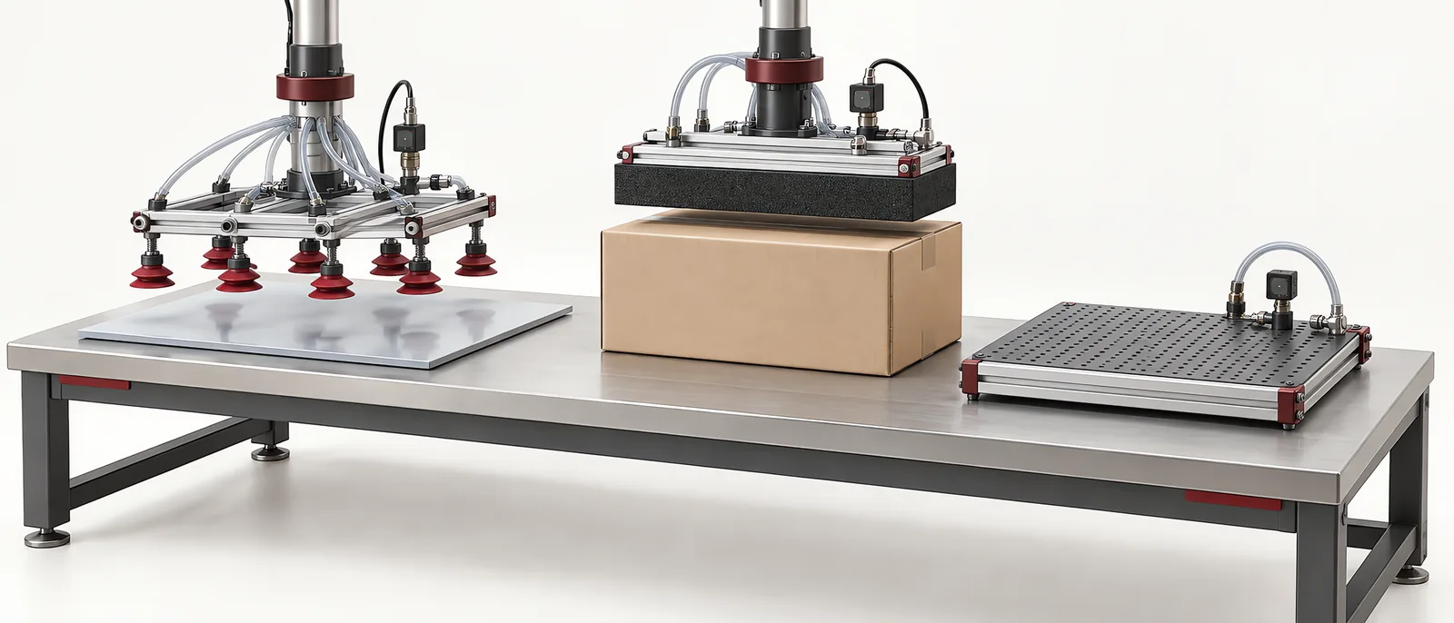
Conceptual equipment illustration.
A vacuum gripper needs to hold the actual product surface through the complete handling motion. For a sealed, smooth panel, pressure difference and effective cup area are central selection inputs. For porous cartons or boards, the vacuum source must also sustain enough flow to cope with leakage.
Start with representative parts from production, including the least favourable surfaces. A clean sample on a bench can hide the effects of cardboard porosity, seams, dust or local distortion.
Match the Contact Pattern to the Part
Individual cups allow their positions to follow usable contact areas. An area gripper spreads contact across a larger face and may accommodate changing product patterns, depending on its sealing and valve arrangement. Neither option makes all uncovered or damaged areas harmless.
| Surface condition | Selection question | Trial observation |
|---|---|---|
| Smooth rigid panel | Can the cups seal without distortion? | Pressure build-up and movement during acceleration |
| Corrugated carton | How much leakage varies between samples? | Holding stability across board and print variations |
| Thin sheet | Where can support prevent excessive bending? | Shape during pickup and release |
| Mixed carton sizes | Which suction zones remain covered? | Effect of exposed ports on the working zones |
| Uneven face | Can the seal follow the permitted geometry? | Local contact and repeatability of pickup |
This surface-level choice feeds into the wider EOAT and gripper design, including tool mass, centre of gravity and robot clearance.
Pressure and Flow Are Different Checks
Vacuum pressure describes the pressure difference available for holding. Flow describes how much air the source can move under the operating conditions. A high ultimate-vacuum figure is not a substitute for the flow needed through a leaking material.
Evaluate the source together with hoses, valves, filters and the gripper. A restrictive hose can slow evacuation; a dirty filter can alter behaviour over time. Locate sensing so that it represents the condition that matters at the gripping system.
Schmalz’s system-design sequence treats force calculation, cups, piping, vacuum generation and switches as connected selections, followed by tests with original parts. Use the same whole-system approach when reviewing a proposed tool.
Diagnose the Stage Where the Pick Fails
Vacuum never reaches the pickup threshold. Check the seal position, uncovered ports, material leakage and restrictions before increasing the waiting time. Compare a known good part with a failed one.
The part lifts but shifts during travel. Examine acceleration, cup spacing, load balance and lateral resistance. More vacuum alone may not solve an unsuitable contact pattern.
The part reaches the destination but releases late. Check venting, blow-off if fitted, trapped volumes and contact with the receiving surface. Include release confirmation in the sequence when a retained part could disrupt the next cycle.
Failures appear after sustained operation. Inspect filter condition, seal wear, contamination and supply behaviour under simultaneous demand. Record the running conditions as well as the failed part.
Confirm the Pick Without Hiding Double Loads
A vacuum signal can confirm that a seal has formed, but it does not always identify how many layers were lifted. Thin sheets or nested items may need an additional thickness, presence or separation check. The part presentation arrangement should make that check possible before the robot carries the product away.
For palletizing systems, trial the weakest carton face and the least supported layer pattern. Include a controlled response to loss of vacuum and verify the complete handling arrangement within the cell’s protective design.
Motionwell’s robot integration scope brings the tool, sensing and machine sequence together. Discuss your handling application.