
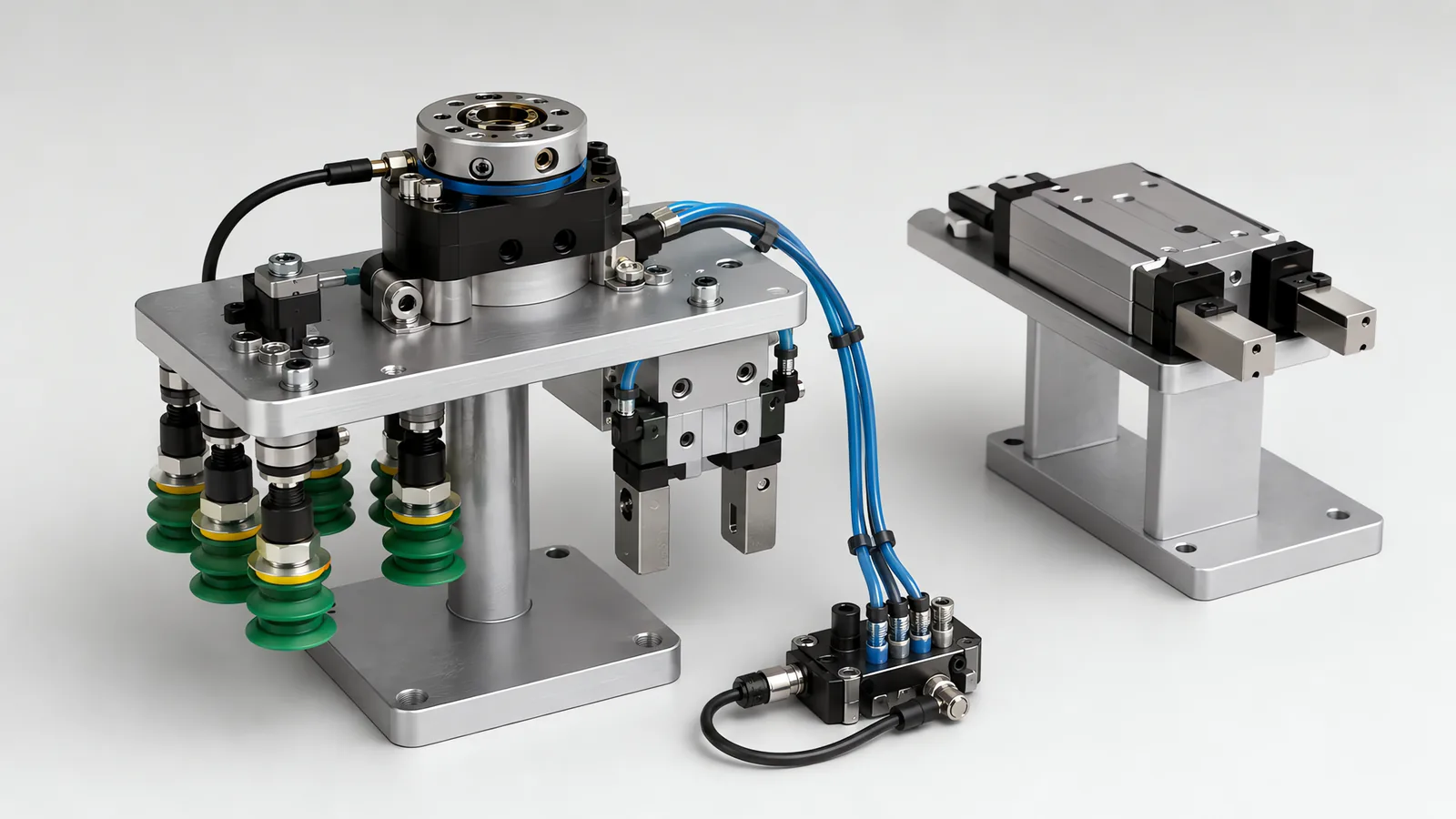
Motionwell Automation designs and builds end of arm tooling in Singapore: the one part of a robot cell that has to be drawn against your product before anything else on the station can be fixed. Four builds cover most of the delivered range.
A 5-magnet electromagnet quick-change tool sits on a cobot unloading station for a consumer goods distribution centre. It switches between electromagnet, pneumatic gripper and vacuum suction with no manual changeover, and carries X and Y pitch adjustment on stepper motors, so one tool covers several product sizes and packaging formats.
On a SCARA sensor panel assembly line, vacuum cups carry pressure-sensor grip confirmation at plus or minus 0.01 mm placement repeatability. The sensor is there for one reason: a panel released mid-move costs more than the sensor and the signal together.
On carton palletizing cells the tooling is engineered per application. A typical build pairs an area vacuum gripper with pneumatic side clamps, so a poorly glued top flap cannot leave the tool holding the flap and dropping the case.
The remaining two are insulated grippers rated for high-voltage DC work on an EV battery disassembly line, and pneumatic grippers on truss manipulators and linear gantries. Tooling is designed, assembled and tested at our Woodlands Link facility, and the company has delivered more than 150 special purpose machines since 2014 under ISO 9001:2015 and bizSAFE Level 3.
The tooling is designed for whichever arm the cell runs, industrial, SCARA, collaborative or mobile, including an arm you already own. What the tool design needs from that arm is its flange drawing, its payload-versus-centre-of-gravity curve and the safety-rated I/O the tool has to sit behind, which are the three things worth asking a robot supplier for before the arm is ordered.
Where a catalogue gripper covers the part at rate we specify one, because a bought unit arrives with a published grip force curve, a wear interval somebody else has already measured and a spares path your storeman can order from. A custom tool earns its cost when the part, the rate or the environment puts it outside what a catalogue body can do. What we design and build is the tool between the arm and your product: the plate, the fingers, the cup layout, the compliance, the sensing, the utilities, and the mounting that has to hold position for the life of the machine.
The palletizing-specific version of the gripper question sits on our automated palletizing systems page, and the arm-selection side is covered in our note on SCARA robots in electronics assembly.
What Are the Types of Robot Grippers, and Which Suits Your Part?
A robot gripper is the device at the end of a robot arm that takes hold of the workpiece and holds it through the move. The same object carries several names: end effector is the formal term, robot hand the everyday one, and end of arm tooling covers the gripper plus the plate, sensing and utilities that make it work on a cell. A screwdriving or dispensing head is an end effector but not a gripper.
Grippers are classified by the physics that holds the part. Get the family wrong and no amount of tuning recovers it, because you are asking a mechanism to do something it was never able to do.
| Gripper family | How it holds | Suits | Where it fails |
|---|---|---|---|
| Vacuum cup or pad | Atmospheric pressure acting over a sealed area | Flat, smooth, sealed faces: cartons, panels, trays, glass, film-lidded packs | Porous, perforated, wet, dusty or deeply textured surfaces, and anything with no usable flat face |
| Bellows vacuum cup | The same physics, with a folded cup that collapses on contact | Domed, angled or uneven surfaces, and picks that need a short lift built into the cup | Lateral stability is poor, so it dislikes fast side moves and overhung loads |
| Parallel pneumatic gripper | Fingers close on air pressure against a mechanical stop | Rigid parts with parallel faces, high cycle counts, hot or dirty environments | No useful control between open and closed; grip force is set by supply pressure |
| Electric gripper | A servo or stepper drives the fingers with position and force feedback | Several part sizes on one tool, delicate parts, cells with no compressed air available | Slower than a pneumatic unit of the same size, and more expensive per axis |
| Magnetic, permanent or electro | Flux across a ferrous face | Steel blanks, stampings, tooling plates, stacked sheet | Non-ferrous parts, thin stacks that lift two at a time, residual magnetism, and a power loss that drops the load unless the design accounts for it |
| Needle gripper | Fine needles drive into the material at opposing angles and lock | Textiles, foam, non-woven and other limp materials that vacuum cannot seal against | Anything that must not be pierced; needles are a consumable with a wear interval |
| Soft or compliant gripper | A flexible finger or bladder conforms around the part | Fragile, irregular or variable items, and mixed shapes handled by one tool | Low grip force, and wear items sitting in the product zone where they are hardest to justify |
Motionwell’s delivered tooling covers the vacuum, pneumatic, electromagnetic and mechanical families. Vacuum end effectors run on the SCARA panel assembly line as cups with adjustable suction force, set high enough to hold the panel through the move and low enough to leave no witness mark on a cosmetic face, which is a narrower window than a cup datasheet suggests. On carton palletizing cells the vacuum and mechanical gripper designs are engineered for each application, and a typical build pairs an area vacuum gripper for carton picking with pneumatic cylinders side-clamping unstable or open-top cases, so the load path runs through the clamps and the vacuum only has to keep the case square. The electromagnetic family is the multi-mode quick-change tool on the FMCG unloading station, where a five-magnet array is one of the three modes the tool switches between on its own.
Mechanical grippers, bought as catalogue units wherever one fits the part, cover trays and totes that give vacuum nothing to seal against, so the tool takes a rim or a flange instead. Pneumatic grippers run on our truss manipulators, including an installation with four picking units, 300 mm Z-axis stroke, 12 metres of Y-axis travel and positioning repeatability of plus or minus 0.1 mm, and multi-finger pneumatic grippers run on the compact three-axis frames in our linear gantry series. Soft-gripper tooling of the bladder and flexible-finger type sits outside that delivered set, and it is the family we specify where it is the right answer: on washdown-duty lines, cobot pick and place with a soft gripper and vacuum end effector is how fragile items get handled gently. Bag and sack tooling is covered on the palletizing page.
For suitable ferromagnetic parts, magnetic handling offers a different contact principle. magnetic gripping choice evaluates the actual part and supply-loss behaviour.
Why Does Part Presentation Decide the Tool More Than the Robot Does?
The mechanisms that deliver a part oriented and on time are covered separately on our part feeding and presentation page; this section is about what that arrival does to the tool.
The tool has to arrive at the part in a known relationship to it, and everything upstream of that moment either establishes that relationship or destroys it. A SCARA holding plus or minus 0.01 mm repeatability is worth exactly as much as the fixture underneath it allows.
Repeatability is not placement accuracy. It describes how tightly the arm returns to a taught point and says nothing about gripper slip, part tolerance, fixture wear or thermal drift, which is usually what you actually measure on the finished assembly. The error budget therefore gets spent somewhere other than the robot: on how well the part is located before the pick, on how repeatably the tool grips it, and on how well the camera is calibrated to the robot frame where vision does the locating.
Three presentation problems change the tool design outright.
Position uncertainty. A part arriving loose in a tote needs a tool with a wide capture envelope and compliance, or a vision system that removes the uncertainty before the pick. On the QA laboratory cell we built, a wrist-mounted camera reads fiducial markers on sample trays and fixtures, calculates the X, Y and theta offset and sends compensation to the cobot before every pick, bringing final placement to within plus or minus 0.5 mm on top of an autonomous mobile robot whose own docking accuracy is far coarser. How that camera is lit, lensed and calibrated is on our machine vision inspection capability page.
Orientation uncertainty. A part that can arrive either way up needs either a feeder that guarantees orientation or a tool and a check that tolerate both. Feeding is where this cost lands: orientation has to be engineered into the feeder against your actual part, and a feeder that presents a wrong-way part every fiftieth cycle costs far more than it looks like it should.
Dimensional spread. Real parts vary. The panel alignment station on the sensor assembly line uses motorised XYZ linear modules with micrometre resolution to compensate for panel warpage and edge trim tolerance that would otherwise propagate into every downstream station, which is what lets one station handle panels of varying thickness and flatness without a dedicated fixture per variant.
Why this belongs at concept stage: redesigning a gripper after the machine is running costs several times more than addressing it during concept review, and on high-mix lines a gripper that loses one particular part orientation is the classic invisible micro-stop, the sort that never reaches a downtime log because nobody records a stop that lasted four seconds.
One Combination Tool or a Quick-Change Tool Rack?
This is the decision that shapes the whole station, and it is settled by changeover frequency.
| One combination tool | Quick-change tool rack | |
|---|---|---|
| Best when | Format changes several times a shift | Changes weekly, or once per production run |
| Cycle time | No tool-change time at all | Every change costs a rack trip and a coupling sequence |
| Design compromise | Every format handled slightly worse than a dedicated tool would | Each tool designed for its own part |
| Payload | Carries every mode’s mass on every pick, whether used or not | Carries only the tool in use, plus the coupler halves |
| Utilities | One fixed dress pack, no live disconnection | The coupler must pass air, vacuum and I/O reliably, and it is a wear item |
| Failure behaviour | One damaged mode takes the whole tool out of service | One tool out, the others keep running |
| Spares policy | One spare tool | Coupler halves, plus a spare of each tool that matters |
| Cost shape | Higher design cost, fewer parts | Lower design cost per tool, more parts, plus the rack and the coupler |
We have built both, and the two delivered examples sit at opposite ends of that table.
The cobot unloading station for a consumer goods distribution centre uses a rack. A carton arrives on a conveyor, a barcode scanner reads the carton ID, and the robot reconfigures to the correct tool set from a tool change rack, with the reconfiguration predefined in the host PLC. It works there because the tool set is selected per carton, and the station is already stopped and clamping the carton while it happens. The same station carries a third answer, the one that rarely appears in a specification: X and Y axis pitch adjustment on stepper motors, sized for the pick spacing each product needs, letting one tool cover several product sizes and packaging formats with no mechanical changeover at all. That is usually cheaper than either a rack or a set of dedicated tools.
The SCARA sensor panel line uses fixed tooling. More than 15 panel variants run with recipe changeover under 3 minutes where robot paths, vacuum grip profiles and vision parameters cover the difference. A variant needing different gripper or tray geometry adds a hardware change and its verification. List those activities for each format transition and measure them together. The same distinction appears in filling line changeover, where tray and closure tooling can change alongside the recipe.
Multiple tools need a defined mechanical and utility connection. tool-changer interface design specifies docking, identity and lock-state tests for the selected changer.
How Do You Budget Payload When the Tool Eats It?
Rated payload is measured at the tool flange, and your tool hangs off that flange. Whatever it weighs comes straight out of the budget before the part gets any.
Do the arithmetic in this order, and write it down where the buyer can see it.
- Tool mass. Mounting plate, gripper body, fingers or cups, vacuum generator or ejector bank, valve island, manifold, fittings, tubing, cable and every sensor mounted on the arm. On a multi-mode tool this is all the modes.
- Part mass at worst case. The heaviest item in the SKU list, including whatever the part is carrying: liquid, packaging, a nest, a carrier.
- Tool centre of gravity. A vacuum plate holding a 400 mm carton pushes the centre of mass well out from the flange, and the resulting moment is what limits the arm. Every collaborative arm publishes a payload-versus-centre-of-gravity chart. Read it before you pick one.
- Inertia at reach. Moment of inertia at full extension is what limits acceleration in practice, which is why a tool that passes a static payload check can still miss the cycle time by a wide margin. A long, light tool can be harder on the arm than a short, heavy one.
- Headroom. If the heaviest part only just fits, it does not fit. Part weights drift and someone will add a heavier one next year.
There is a related trap in the cycle time. A datasheet cycle time is measured on a fixed gate-to-gate move with a dummy load and nothing else happening. The real cycle adds vision acquisition and processing, settling time before the vacuum releases, gripper actuation time, and the handshake with the PLC. Those additions are usually what decides whether the station makes rate, which is why we time them on the actual parts before quoting a throughput figure.
How Is a Vacuum Tool Sized, and Where Does It Leak?
Vacuum holds by pressure difference acting across sealed area, so sizing is a matter of sealed area, achievable vacuum level and the acceleration the part will see, with a safety factor that reflects how bad a dropped part is. Horizontal picks are the easy case. A cup gripping a vertical face carries the load in friction, and that is a different and much less forgiving calculation.
Start fault finding at the seal and leak paths, then check the source flow available through the installed hoses and filters. Porous products can need substantial continuous flow even with a suitable contact pattern.
| Surface or condition | What happens at the cup | Usual fix |
|---|---|---|
| Corrugated, embossed or heavily textured board | Air tracks along the flutes under the lip, so the cup never seals | Larger cup on a flat panel area, foam pad spanning the texture, or add mechanical clamping |
| Poorly glued carton top flap | The flap lifts, the cup holds the flap | Pneumatic side clamps carrying the load, with vacuum only assisting |
| Wet or condensing surface | Water film breaks the lip seal, and the cup slides before it lets go | Move to a mechanical grip, or a tool that gets underneath the part |
| Dusty or powdered surface | Dust bridges the sealing lip and abrades it, so performance decays over weeks | Dust-tolerant cup profile plus a filter before the generator, and a cup replacement interval |
| Porous product: fabric, foam, unsealed board | Air passes straight through, so no differential builds | Needle gripper, clamp or a high-flow generator sized for the leak |
| Perforated or vented packaging | Same effect, concentrated at the holes | Reposition cups off the vent pattern, which means the pack drawing has to be seen at design stage |
| Cup landing partly off the part edge | Intermittent drops that pass every static test | Tighten part presentation, or add a part-present check before the lift |
| Aged or hardened cup lip | Gradual loss of grip that nobody attributes to the cup | Cups on a scheduled replacement interval, treated as consumables |
Two design rules follow from that table. First, verify the grip. On the SCARA panel assembly line the vacuum level is monitored by a pressure sensor that confirms grip before the robot initiates movement, which converts a dropped panel into a held cycle plus an alarm. Second, size a multi-pick head so the worst cup in the array still holds. A group tool that brings back all but one item has not worked.
Vacuum generators and valve manifolds are bought in, and the choice between a central pump and distributed venturi ejectors is decided by duty cycle and by how much air you are willing to pay for. A central pump earns its place on near-continuous high-flow duty, because one motor moving air costs less to run than a bank of ejectors sized for the same flow. Distributed ejectors earn theirs on intermittent picks, because vacuum builds and vents at the cup, and that is response time. An ejector running continuously on a leaky surface is an expensive way to heat a factory.
The vacuum gripper troubleshooting guide separates seal formation, movement during travel and delayed release. For porous material, compare pressure and available flow together through the actual hoses, filters and valve arrangement.
What Utilities Have to Reach the Tool, and How Do They Get There?
More than people expect, and routing them is a real part of the design. A typical multi-mode tool needs compressed air, a vacuum line or a local generator, 24 V power for solenoids and sensors, discrete or fieldbus I/O for grip and part-present signals, and sometimes an additional service such as adhesive, ionised air or a camera trigger.
Three constraints decide how that bundle is routed.
Rotational limits. A wrist axis that rotates through a large angle will wind a dress pack, and the axis travel limit that follows is discovered during programming unless someone checks it first. Reach and clearance get verified in offline simulation before the cell is built, and the dress pack belongs in that simulation.
Flex life. Continuous-flex cable inside an energy chain rated for the travel is the standard answer, and on cleanroom and long-travel builds the chain and the cable are specified against the actual bend radius and cycle count, because a jacket chosen only to fit is the one that crazes after a few million cycles. Bend radius has to be respected. A jacket cracked at a tight bend is a failure that reappears every time it is patched.
The coupling, where there is one. A quick-change interface has to pass air, vacuum and electrical signals across a joint that separates and rejoins thousands of times. That joint is a wear item with a maintenance interval, and it is the component that decides whether the rack approach stays reliable in year three.
On gantry builds the same problem appears at a different scale, with energy chain carrying the tool services along the full stroke, as on the linear gantry robots we build for CNC machine tending. Long travel sharpens it: a truss manipulator with twelve metres of Y-axis travel has to deliver air and signals to a tool that never stops moving. That is why the chain, its fill and the service routing get sized alongside the tool.
What Changes When the Tool Works in a Cleanroom or a Washdown Zone?
The physics of the grip does not change. Everything around it does, and the constraints pull in different directions, which is why one tool rarely serves both environments.
| Design aspect | General industrial | Cleanroom tooling | Washdown tooling |
|---|---|---|---|
| Materials | Aluminium, mild steel, standard polymers | Anodised aluminium and stainless; PEEK, POM, UHMWPE and PTFE behave, nylon is hygroscopic and swells | SUS304/316 on contact faces, seals chosen against the cleaning agent |
| Surface finish | Whatever machining leaves | Smooth and wipeable, crevices designed out, no blind holes | Ra 0.8 um or better on contact surfaces, sloped so water runs off |
| Fasteners and joints | Exposed heads acceptable | Countersunk or counterbored, welds ground flush, unused threads plugged | Continuous welds, no horizontal ledges, tool-free removal of contact parts |
| Pneumatics | Muffler on the exhaust port | Cleanroom-rated cylinders with exhaust ducted out of the clean zone entirely | Sealed actuators, drain paths, no traps that hold rinse water |
| Cabling | Standard cable and nylon ties | Low-outgassing continuous-flex cable, glanded entries, stainless cable ties | IP-rated connectors and glands, cable runs that drain |
| Lubrication | Standard grease | PFPE cleanroom grease in sealed bearings, specified by quantity and interval | Incidental-contact lubricant, applied sparingly |
| What kills it | Wear | Particle count | Water ingress and residue trapped in a crevice |
Two points get missed on almost every cleanroom tooling review. A standard cylinder with a muffler on its exhaust port vents oil-laden air into the room on every stroke, at the exact moment and position the tool is over the product, which usually makes it the single largest particle source on a machine and the easiest to miss on a schematic. And powder coat, which is fine on a Class 8 enclosure, is a liability on tooling above that, because chipped coating is a particle source that grows over the machine’s life. The full treatment is in our cleanroom automation design guide.
On the washdown side, be precise about what the rating covers, and set it from the cleaning routine. An IP65 enclosure covers dust ingress and low-pressure water jets, so hose-down and wipe-down sanitation between shifts is fine. IP65 is not a high-pressure or steam-cleaning rating, and if your sanitation procedure uses high-pressure jets or caustic foam followed by a pressure rinse, that has to be on the specification before the tool is drawn.
Does the Tool Change the Safety Case on a Cobot Cell?
Yes, and it is the part of a collaborative application that gets assessed last and should be assessed first. A collaborative robot is not the same thing as a collaborative application: a force-limited arm says nothing about the tool, the part, or what happens when the grip fails.
ISO 10218-1 was revised in 2025, the third edition and the first substantive revision since 2011. It adds robot classifications with matching functional safety requirements, safety-related cybersecurity requirements, and end-effector guidance, while most of what ISO/TS 15066:2016 said about collaborative operation moved into Part 2. It references the 2023 edition of ISO 13849-1 for control system safety functions, the standard each safety function on the cell is rated against for performance level, so a tool interlock or a grip-retention circuit still documented to the 2015 edition will need its performance level calculation restated when the cell is reassessed. If you are writing a safety file this year, check which document your assessment is citing before it is issued.
Three tooling decisions carry most of the risk.
Geometry. Long, thin or pointed end effectors concentrate contact force, and some geometries simply cannot pass a transient contact assessment at any speed worth running. Contact limits have to be validated against your actual end effector and workpiece. A compliant fingertip or a rounded bracket edge can move a contact scenario from unacceptable to workable, and it costs almost nothing at concept stage.
Grip loss. Power and force limiting does not address a part dropped from height. That hazard is handled with fixed guarding, a catch tray, a mechanically retained grip, or a design where loss of air or power does not release the load.
Energised or hazardous workpieces. On the EV battery disassembly line the workpiece cannot be switched off, so the tooling itself carries the insulation. All robot end effectors and gripping tools on that cell are rated for operation in high-voltage DC environments up to 1,000 V, with an aramid paper wrap on metallic gripper fingers and tool plates, a fibreglass laminate bracket carrying the load between the robot flange and the tool body, and an insulating liner on every fixture surface that can touch a module terminal. The rating is the easy half. Insulation resistance is verified weekly with a 1,000 V DC megohmmeter and any tool reading below 100 megohm comes out of service, because what protects anyone is the re-test interval: a wrap abraded by a fastener head or wetted by electrolyte still looks intact. That is what it looks like when tooling is a safety function, and the wider method is on our machine safety and CE compliance page, with the collaborative-specific assessment in our guide to cobot safety standards.
How Is End of Arm Tooling Validated Before It Ships?
Tooling is validated on the worst case, and the acceptance evidence is a distribution.
Every pick should assert something in the cycle: vacuum level above threshold, gripper finger position within band, part-present sensor made. A tool that reports only “commanded” produces silent failures that surface three stations downstream. The parts it asserts against matter as much as the assertion. Run the lightest, heaviest, most warped, wettest and dirtiest items you can find, plus the ones from the supplier batch everyone complains about, because a tool proven on good parts has been proven on the wrong population.
Placement gets measured under load at the far end of the working envelope, since that is where compliance in the tool, deflection in the plate and inertia in the arm all show up together. Accuracy is a property of the whole stack, so a number taken near the base of the arm with an empty tool tells you very little about the corner of the pallet.
Then there is cycle count before shipment, which exists for the consumables. Cup lips, finger pads, needles, coupler seals and cylinder seals all have a wear interval, and the value of a soak test is that it turns that interval into a number the maintenance schedule can carry.
Where the tool does work as well as holding, the process signature is the record. On the SCARA panel line torque-controlled electric screwdrivers work to a target set per fastener in the recipe, with the result logged for every fastener against the panel serial number and out-of-window fasteners rejected immediately.
The place for all of it is factory acceptance testing at our Singapore facility before shipment, which is the practical argument for a Singapore buyer working with a Singapore builder: tooling gets adjusted more often than any other part of a machine, and those adjustments happen in hours when the builder is in the same industrial estate.
What Drives the Cost and Lead Time of Custom End of Arm Tooling?
Custom gripper cost follows the part range, load budget, actuation, sensing and changeover arrangement. Price those requirements with the verification and spare-tooling scope so the quotation covers the complete duty.
| Cost driver | Why it moves the number |
|---|---|
| Number of part formats one tool must cover | Every additional format is either a compromise, an adjustment axis, or another tool in a rack |
| Quality of part presentation | A part located by a fixture is cheap to grip; a part loose in a tote needs vision, compliance and a wider capture envelope |
| Grip verification depth | A commanded output costs nothing; vacuum level, finger position and part-present sensing each add a device and a signal |
| Adjustment axes on the tool | Motorised X and Y pitch adjustment buys format flexibility and brings motors, cabling and a homing routine with it |
| Quick-change scope | Coupler halves, a rack, docking repeatability and a maintenance interval, versus one fixed plate |
| Utilities through the arm | Air alone is simple; air plus vacuum plus fieldbus plus a camera trigger is a dress pack design |
| Environment | Cleanroom and washdown builds change materials, finish, fasteners, seals and lubricants across the whole tool |
| Safety scope | Insulated, force-assessed or catch-protected tooling is engineering plus documentation |
| Payload headroom | A tool that has to be light to fit the arm drives material choice, machining time and analysis effort up |
Lead time for the tooling follows the machine it belongs to. On a standard build the programme runs 16 to 24 weeks from concept approval to factory acceptance testing, and 24 to 32 weeks where cleanroom compatibility or full GMP validation applies. How a project of this shape is scoped from concept to commissioning is set out in our guide to special purpose machine design.
What Do We Build, and Where Is a Catalogue Gripper the Better Answer?
Being specific about this is more useful than a capability claim.
We design and build the tool: plate, fingers, cup layout, compliance, sensing, pneumatics, utilities routing, the quick-change interface where one is justified, and the control logic that verifies the grip. We design tooling for whichever arm the cell runs, including arms you have already bought and hand to us. The arm changes the flange pattern, the payload curve and the I/O the tool sits behind; it does not change the tooling method. Delivered tooling includes the multi-mode quick-change tool on the FMCG and co-packing unloading station. It includes custom precision grippers on the vision-guided SCARA panel assembly line, combining a rigid locating block with a compliant gripping face. And it includes a custom end-of-arm tool with pneumatic torque control and cap presence verification on a vial capping and uncapping station, and vacuum-assisted mechanical grippers with load cells confirming module weight before transfer on the EV battery line.
We build against a specification and support your conformity work, including LVD and CE testing and MOM lifting certification where the machine includes lifting equipment.
A catalogue gripper wins whenever the part is rigid, the faces are parallel or flat, the rate is inside the published curve and the environment is ordinary. Buying one brings a grip force curve, a wear interval somebody else has measured and a spares path your storeman can order against, and none of that has to be re-established from scratch. We specify catalogue units on our own builds for exactly that reason, and we will say when your part is one of those cases before the design work starts.
Standards Used in Machine Design and Validation
These references inform the design, testing and documentation described on this page. Each row links to its primary source and records the edition checked.
| Standard | Current edition | What it means for your machine |
|---|---|---|
| ISO 10218-1: Robotics, safety requirements, Part 1: industrial robots | ISO 10218-1:2025 | Published February 2025, the third edition and the first substantive revision since 2011. It adds robot classifications with matching functional safety requirements and safety-related cybersecurity requirements. Most of ISO/TS 15066:2016 on collaborative operation moved into Part 2.Checked 12 Sep 2026 against ISO 10218-1:2025 (iso.org/standard/73933.html) |
| ISO 13849-1: Safety of machinery, safety-related parts of control systems | ISO 13849-1:2023 | Provides the design method for safety-related control functions, including architecture, component reliability, diagnostic coverage and common-cause failure measures. The machine risk assessment establishes the required Performance Level; design calculations and validation provide the evidence for each function.Checked 1 Sep 2026 against ISO 10218-1:2025 normative references |
Frequently Asked Questions
How do I work out the real payload budget for an end of arm tool?
Start from the tool. Rated payload is measured at the robot's tool flange, and everything hanging off that flange comes out of the budget first: gripper body, fingers or cups, vacuum manifold and ejectors, valves, cabling and any sensor mounted on the arm. Then add the heaviest part you will ever handle. Check that total against the arm's payload-versus-centre-of-gravity curve at your real tool centre of mass and your real reach, because the moment at full extension limits acceleration long before mass does. If the heaviest case only just fits, it does not fit, because part weights drift and someone will add a heavier item next year.
Should I build one combination tool or use a quick-change tool rack?
Changeover frequency decides it. Four format changes a shift argues for one combination tool that compromises on every format, because every rack trip costs cycle time and every coupling is a wear item. Weekly changes argue for the rack, because each tool is then designed for its own part. A third option is often cheapest and gets overlooked: keep one tool and make it adjustable. On our cobot unloading station for a consumer goods distribution centre, X and Y axis pitch adjustment on stepper motors lets one tool cover several product sizes and packaging formats with no mechanical changeover at all.
Why does a vacuum gripper drop parts intermittently?
Almost always a leak path. A cup holds by pressure difference across a sealed area, so anything that lets air back in defeats it: a porous or fibrous surface, condensation or product film under the lip, a badly glued carton top flap, a perforated or heavily embossed face, a cup landing partly off the edge of the part, or a lip that has hardened with age. Diagnose it by monitoring vacuum level. On our SCARA panel assembly line a pressure sensor confirms grip before the robot initiates movement, which turns a dropped part into a held cycle and an alarm.