
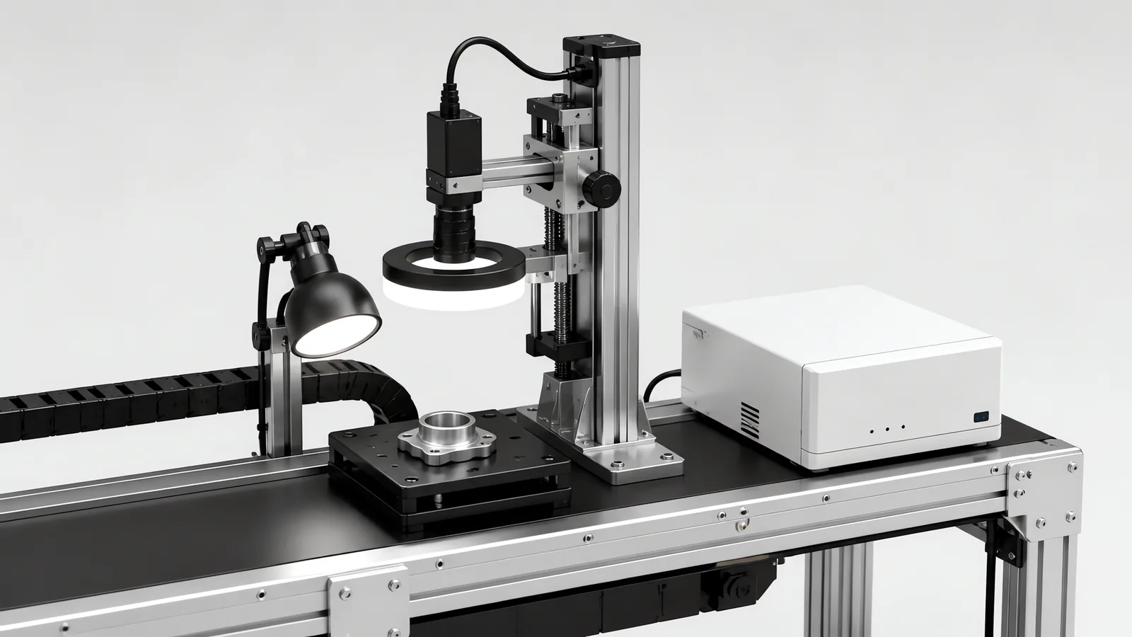
Motionwell Automation integrates machine vision inspection into custom machines and existing production lines in Singapore. Delivered systems include inspection inside cleanroom automated test equipment, vision working alongside a collaborative robot in a QA laboratory cell, and a copper-plate thickness measurement machine where the reading is taken by laser displacement, because a thickness is a height and a camera can only infer a height from what the light does to the surface. The same station design becomes a vision gate on a multi-station rotary assembly machine, placed before each irreversible step with the result tied to the nest position; where those gates belong on a dial is set out in our guide to how we design multi-station rotary assembly machines.
A machine vision inspection system is a camera, a lens, a light source and a processor that makes a pass, fail or measurement decision on every part while the line runs, then hands that decision to the machine controller so something physical happens: a pusher fires, a gate diverts, a record is written. The camera is the cheap part. The engineering sits in the lighting, the fixture that presents the part the same way every cycle, and the handshake that makes the result act before the part is gone.
That description holds across industries, and this page stays at that general level. Where the question is electronics-specific, meaning sizing a camera across a panel, connector pin coplanarity, or mixed surface finishes in one field of view, the detail is in our separate guide to vision inspection for electronics.
This page is written from the integrator’s side of the table: choosing hardware, lighting the part, knowing what vision cannot see, and tuning the false-reject trade-off so operators do not switch the station off. If you already have parts and a defect list, talk to an engineer.
What Is Machine Vision, and How Does It Work?
Machine vision is automated visual inspection under controlled conditions. Every system, from a single smart sensor to a multi-camera line, runs the same chain:
- Trigger. A sensor, encoder pulse or PLC output tells the camera a part is in position. Everything downstream inherits the trigger’s jitter.
- Illumination. A light fires, usually strobed, creating contrast between the feature you care about and everything else.
- Capture. The lens projects the scene onto the sensor. Blur length is roughly part speed times exposure time, so a moving part forces a short exposure, which forces more light.
- Processing. Software locates the part, applies measurement or defect tools inside regions tied to that located position, and produces numbers: an edge distance, a match score, a blob area, a code grade.
- Decision. Those numbers are checked against limits, and a pass/fail bit plus the measured values go to the PLC over EtherNet/IP, PROFINET or digital I/O.
Step 4 gets all the attention in marketing material. Steps 1 to 3 cause almost all the field failures.
Is Machine Vision a Type of AI?
They are different kinds of category, which is why a straight yes or no misleads. Machine vision names an engineering setup, defined by the controlled conditions in the chain above: a fixed camera, a fixed light, a part held in a known position, a verdict inside the cycle. AI names a family of processing tools, and those tools can occupy step 4. A station is machine vision either way, and swapping a measured edge distance for a trained model leaves the trigger, the illumination and the optics exactly as they were, along with whatever they failed to capture.
The inspection we have delivered is rule-based. An engineer states the feature in geometric terms and the software measures it: pattern matching with edge detection for presence and orientation on a sensor panel line, and no model was trained for it. On a multi-station rotary assembly machine we would take the same route, contour recognition under dome lighting at the inspection station and OK/NG sorting into separate reject bins at the unload station. Deep learning tools ship inside the same vendor packages we already buy, so the choice arrives as a tool selection on one station and not as a platform decision for the whole line.
What separates the two in service is who owns the decision afterwards. A rule has parameters a technician can read off the configuration and re-test on a disputed part. A trained model puts the decision in weights, so the plant owns a labelled image library and a retraining procedure instead, and on a validated line every retrain is a change to defend. That commitment is worth deciding on deliberately, and the full comparison sits on our surface defect inspection page.
Machine Vision vs Computer Vision
The distinction is practical. Computer vision is the general problem of extracting information from images, often in scenes nobody controls. Machine vision is the industrial subset: fixed camera, fixed lighting, a part held in a known position by a fixture we designed, and a decision that lands inside a cycle time with a deterministic output.
That constraint is a feature. A line does not need a clever answer, it needs the same answer at 3 a.m. with a different operator and a different lot of material. Much of the integrator’s job is removing variation until the vision problem becomes easy.
Should You Use a Smart Camera or a PC-Based System?
This is the first hardware decision, and it sets your spare-parts strategy for the next decade.
| Smart camera | PC-based vision | |
|---|---|---|
| Where processing runs | Inside the camera body | Industrial PC in the cabinet |
| Who adjusts it later | A trained plant technician, in a vendor GUI | Someone who writes software |
| Cabinet impact | Low power, low heat | PC, storage, UPS, thermal load |
| Image archiving | Limited onboard storage | Full-resolution images to disk or server |
| Best fit | Presence, code read, label check, simple metrology | High resolution, multi-view, classification |
We specify smart cameras for most stations because the maintenance story is better, and the maintenance story is what decides whether a station survives its second year. When a smart camera dies at 2 a.m., a technician swaps the body and reloads the stored recipe, and the line is back on the same shift. When a PC-based system dies, recovery needs the drive image, the licence and the matching software version, and if any of the three is missing or a revision out of step, the station comes back scoring differently from how it scored at buy-off, which is worse than a station that is still down, because a station that is down gets attention and a station that drifted does not. That difference is a specification decision: it sets what the store has to hold and who has to be reachable to use it. PC-based wins when several cameras must see one part in the same instant, when resolution outruns a smart camera sensor, or when the quality system requires an archived image of every part.
What Are Cognex’s Machine Vision Systems?
Cognex is a vision platform an integrator buys in, so the answer worth giving here is the selection rule: what has to be true on a station before Cognex goes on it. On a station that is otherwise a straight presence, position or code check, the platforms in this class are close enough on capability that two service questions decide it instead, and neither of them appears in a tool list: how long it takes a plant technician to set the station up and re-teach a recipe after a product change, and whether there is an application engineer in your own time zone the week the station starts drifting. A platform that wins on tools and loses on both of those produces a station nobody on site can maintain.
Three conditions decide the platform outright.
Code grading is the deciding tool. Serialization work, where grading a printed DataMatrix against ISO/IEC 15415 matters more than defect tooling, is the case for a dedicated Cognex reader. When the station’s job is reading and grading a GS1 code, it is a reader specification and we write it as one.
A trained classifier is genuinely the right answer. Cognex In-Sight is the usual answer when the defect can only be shown by example. It also matters at this branch of the decision that In-Sight is a smart-camera-class device, so wanting classification does not by itself push the station onto a PC. The architecture question is separate, and it is worked through on our smart camera vs PC-based vision page.
Your plant already stocks one brand. If the maintenance store carries one platform’s bodies, cables and licences, staying on it is a sound reason, and we build the station around what you hold.
Platforms in this class all present the machine with the same interface: trigger in, result out, recipe selected by the PLC. The brand decides who you call for support and what sits on the spares shelf, and it leaves the fixture, the lighting and the handshake untouched. Those decide whether the station holds up.
Moving-camera installations need the right cable construction as well as the right interface. machine vision cable selection separates fixed, drag-chain and torsional use.
Visible joint appearance and required electrical function need distinct evidence. solder-joint inspection defines the process and complementary checks for an electronics joint.
Why Does Lighting Decide Whether the System Works?
If a defect is not visible in the raw image, no amount of processing recovers it. Lighting is not an accessory to the camera. It is the measurement instrument, and the camera only records what the light reveals.
Contrast comes from geometry. The same scratch is invisible under flat front light and obvious under grazing illumination: light striking a raised edge at a low angle scatters back toward the lens, while the flat surface reflects away.
| What you need to see | Lighting approach | Mechanism |
|---|---|---|
| Scratch, dent, emboss, surface texture | Low-angle dark field ring | Grazing light scatters off height changes only |
| Presence, outline, edge position, dimension | Backlight | Silhouette; contrast independent of surface colour |
| Print, label text, code on glossy or curved surfaces | Diffuse dome | Removes specular hotspots that break OCR |
| Flatness or marking on a mirror-like surface | Coaxial on-axis | Light returns along the lens axis |
| Parts moving at line speed | Strobed LED tied to the trigger | Short pulse freezes motion |
Two rules on every build. Shroud the station so factory ambient light and sunlight through a roller shutter never reach the field of view, because a station that drifts between day and night shift is almost always an ambient light problem. And fix the part mechanically: a camera cannot compensate for a part that rocks in its nest, and it reads that rocking as dimensional variation and scraps good product. On a multi-station rotary assembly machine, nest design usually takes longer than vision setup, because every nest on the dial passes the same camera and any difference between nests shows up as part variation.
Lighting selection should compare real acceptable and defective samples. LED lighting geometry trials checks contrast geometry before brightness and includes moving-part trials.
How Do You Choose Optics and Working Distance?
Field of view and pixel count set the nominal sampling scale at the part. Working distance, lens focal length and sensor size determine the optical geometry. Select them together with space for lighting, focus adjustment and the depth variation of the product.
Start from the smallest feature you must reliably detect. Divide field of view width by horizontal pixel count to get millimetres per pixel. A widely used industry rule is that the smallest defect needs at least three pixels across it, and more when contrast is low, because a one-pixel feature is indistinguishable from sensor noise. Work backwards to the sensor, then pick a focal length giving that field of view at a working distance the machine frame can accommodate.
- Depth of field: closing the aperture deepens focus and cuts the light reaching the sensor, pushing you toward more illumination or a longer exposure. On parts with height variation, depth of field is often the binding constraint.
- Perspective error: a standard lens images the top of a tall part at slightly different magnification than the bottom, so a dimensional check reads differently as the part shifts. Telecentric lenses remove that change and are the normal choice for measurement.
- Mounting: the lens has to clear the robot envelope, the gripper swing and the operator’s hand, so the vision layout freezes with the machine layout.
Not every measurement problem is a camera problem. Plate thickness needs a sensing arrangement that establishes both material surfaces or an appropriate reference. A single laser displacement reading measures surface position; it does not by itself establish thickness. Opposed displacement sensors are one option, while other materials and geometries may require a different qualified method. Leak testing gets pressure sensing, because a leak has no visual signature at all, and a camera aimed at a sealed part will report a good part every cycle. Picking the sensor that suits the physics is part of the job, and getting it wrong buys a precise measurement of the wrong physical quantity.
The machine vision lens selection guide works through field of view, working distance and object-space sampling, then defines a trial across the allowed part positions and heights.
Camera selection connects motion during exposure with the trigger and data path. The camera acquisition guide includes a blur calculation and acquisition tests.
Thickness requires a defined relationship between two material surfaces. The thickness measurement geometry distinguishes opposed sensing from displacement and includes a geometry example.
What Defects Can Vision Catch, and What It Cannot?
Vision reliably catches anything that makes a repeatable difference in the image under controlled light:
- Presence and absence of a component, screw, seal, gasket or insert
- Orientation and correct part variant before an irreversible step
- Dimensional checks in the image plane against a calibrated scale
- Surface defects: scratch, dent, burr, flash, contamination, discolouration
- Barcode and DataMatrix reading plus print quality grading
- Fill level, cap presence, cap skew and seal defects on filled containers, as covered on our filling machines capability page
- Weld bead surface geometry: bead width, spatter, undercut, surface-breaking porosity. We integrate the inspection only
Vision cannot see through material. Subsurface porosity, internal voids, delamination and cracks under coating need X-ray, ultrasonic or CT. Leaks need pressure decay or tracer gas. Torque, force and continuity need their own instruments. Vision also performs badly against defects with no consistent visual signature: a contamination class that sometimes reads as a shadow and sometimes as nothing at all gives you a station that passes buy-off and drifts afterwards.
So the first step of any vision project is imaging your real parts, including known-bad ones from every defect class. If a defect cannot be shown to the camera in a way an engineer sees on the monitor, it will not be caught in production. Our vision inspection guide for electronics covers resolution sizing in more depth.
What Does a Label Inspection System Check?
Label inspection is a common first vision project: the defect is visible, the payback is obvious, and a mislabelled unit is a regulatory problem in medical device production and pharmaceutical packaging. A label inspection system typically verifies:
- Presence and position: the label applied, within skew and placement tolerance, with no lifted corners or wrinkles.
- Correct variant: artwork matched against the batch recipe, which catches the classic changeover error of running yesterday’s label on today’s product.
- Print legibility: OCR or pattern matching on lot code, expiry date and product name, with OCV confirming the printed string equals what the line was told to print.
- Code quality: barcode and 2D code decoded and graded, so a code that still scans but is degrading gets flagged before it fails at a distributor.
The hard part is rarely the reading. It is presenting a curved, glossy, sometimes translucent surface to the camera consistently while the container moves, which is a lighting and handling problem before it is a software one.
Printed-code inspection needs both readable characters and the correct value. OCR and expected-value checks separates OCR, verification and the physical reject path.
How Do You Balance False Rejects Against False Accepts?
Every inspection tool produces a continuous score (a match percentage, a blob area, an edge distance) and a threshold turns it into pass or fail. Tighten it and you fail more good parts. Loosen it and escapes rise. No setting removes both; there is only the setting that fits the cost of each error.
Those costs are not symmetric. Where an escape can reach a patient or trigger a recall, the threshold sits tight and scrap is accepted. On high-volume consumer goods, a false-reject rate of a few percent eats the margin, so the threshold loosens and a manual check catches the rest.
How we set it:
- Collect a real sample set including borderline parts. Clean good parts and obvious defects say nothing about where the threshold belongs. The marginal parts define it.
- Grade that set by hand first, ideally with two inspectors. If experienced people disagree on a part, the vision system will not be more consistent than the specification it copies.
- Plot the score distributions for good and bad. The overlap is the real information: heavy overlap means the lighting or optics needs rework, and never that the threshold needs a nudge.
- Set the threshold, then validate it against a held-back sample the station has never seen.
- Log every reject with its image and score, or nobody can say later whether a rising reject rate is a process problem, a lighting problem, or a drifting threshold.
A failure mode we see repeatedly is a station tuned for zero escapes on marginal illumination. Reject rate climbs, production falls behind, and someone eventually widens the limits until everything passes. A station operators trust beats one that is theoretically stricter.
Learned inspection tools need representative labels and independent test samples. AI inspection data and acceptance separates model evidence from physical rejection and missing-result handling.
How Does Vision Connect to Rejects and Traceability?
A pass/fail bit that nothing acts on is a screensaver. The mechanical and data side is where the station earns its keep.
Reject actuation. Pneumatic pushers and air blasts suit small parts at speed, diverter gates and drop flaps suit larger items, and a robot pick-off handles parts that must be placed, or rejects segregated by defect class. We build these from catalogue pneumatic components that a local distributor stocks, driven by the machine’s own PLC, because a reject device waiting on an imported cylinder is a reject device somebody bypasses to keep the line running.
Reject confirmation. The reject device needs its own sensor proving the part actually left the line. Without it, a stuck pusher silently passes every failed part downstream while the log still records a rejection. On regulated lines that sensor is not optional.
Timing. Several stations usually sit between camera and reject point, so the PLC carries each result along with its part in a shift register indexed to the conveyor encoder or machine cycle. Get this wrong and rejects land one position off, which looks like a vision fault and is not one.
Data. Results go to CSV, a database or an MES. On a serialization line the coder and the reader should form one closed loop: every code printed, read back, graded and bound to the unit record. For a medical device manufacturer we delivered an electronic device history record system as a standalone order, now rolling out site by site, so inspection results attach to the unit’s build history. Where 21 CFR Part 11 applies, audit trail and controlled retention get designed in.
The cleanroom automated test equipment case study shows the pattern inside an enclosed, fan-filtered machine: cobot loading, fixture test, inspection, logging, segregated output.
Visible presence and location checks may not measure deposit quantity. inspection of jetted deposits separates the jet-process window from the inspection characteristic.
What Should You Expect From a Machine Vision Integrator in Singapore?
Motionwell delivers a complete inspection station: camera, lens and lighting selected for your defect, a fixture and motion system that control part presentation, configured vision tools, PLC logic and reject handling. We test the sequence on your parts against the agreed detection, measurement and cycle-time requirements.
Vision is usually one station inside a larger machine we are building anyway: an assembly cell, a robot cell, a test rig, a filling line, or a retrofit whose control system we are modernising. That is where integration quality matters most, because the camera shares a cabinet, a network, a safety circuit and a cycle time with everything else. We work from Woodlands Link with an in-house design team of eight, ISO 9001:2015 certification and bizSAFE Level 3. Our guide to selecting a system integrator lists the questions worth asking any vendor, including us.
For product and sensor selection, the 2D vs 3D vision guide starts with the measured feature, and the Cognex vs KEYENCE comparison uses matched sample trials. The machine vision vs computer vision guide explains why an image-processing result alone does not define a production inspection system.
Application interfaces then shape the station. Vision guided robotics converts a calibrated observation into a robot target. A laser marking machine needs the physical mark checked against assigned data; a label inspection system separates label appearance, product identity and variable text.
Frequently Asked Questions
What does a machine vision integrator actually do?
An integrator selects the camera, lens and lighting for your specific defect, mounts them so the part presents itself identically every cycle, writes the PLC handshake, and connects the pass/fail result to a reject device and a data record. Motionwell configures proven vision tools and tests the complete inspection sequence on your parts at the required line speed.
Should I choose a smart camera or a PC-based vision system?
Start with a smart camera. A self-contained unit that does its own processing handles presence checks, code reading, label verification and straightforward measurement, and a plant technician can adjust it without a software engineer, which is what decides whether the station is still switched on a year later. Move to a PC-based system when you need several synchronised high-resolution cameras, an archived image of every part, or a classification task the vendor toolset cannot express. Putting a PC on a job a smart camera does adds an operating system, a licence and a drive image to the machine spares list, and each of those is a way for the station to be down on a night shift.
Why does lighting matter more than camera resolution?
Lighting creates the contrast the camera must resolve. Low-angle light can reveal scratches, backlight defines an edge and diffuse illumination reduces glare on glossy surfaces. Resolution still matters: the smallest defect needs enough pixels and contrast for the chosen detection method. Test lighting, optics and part presentation together using good, defective and marginal samples.