
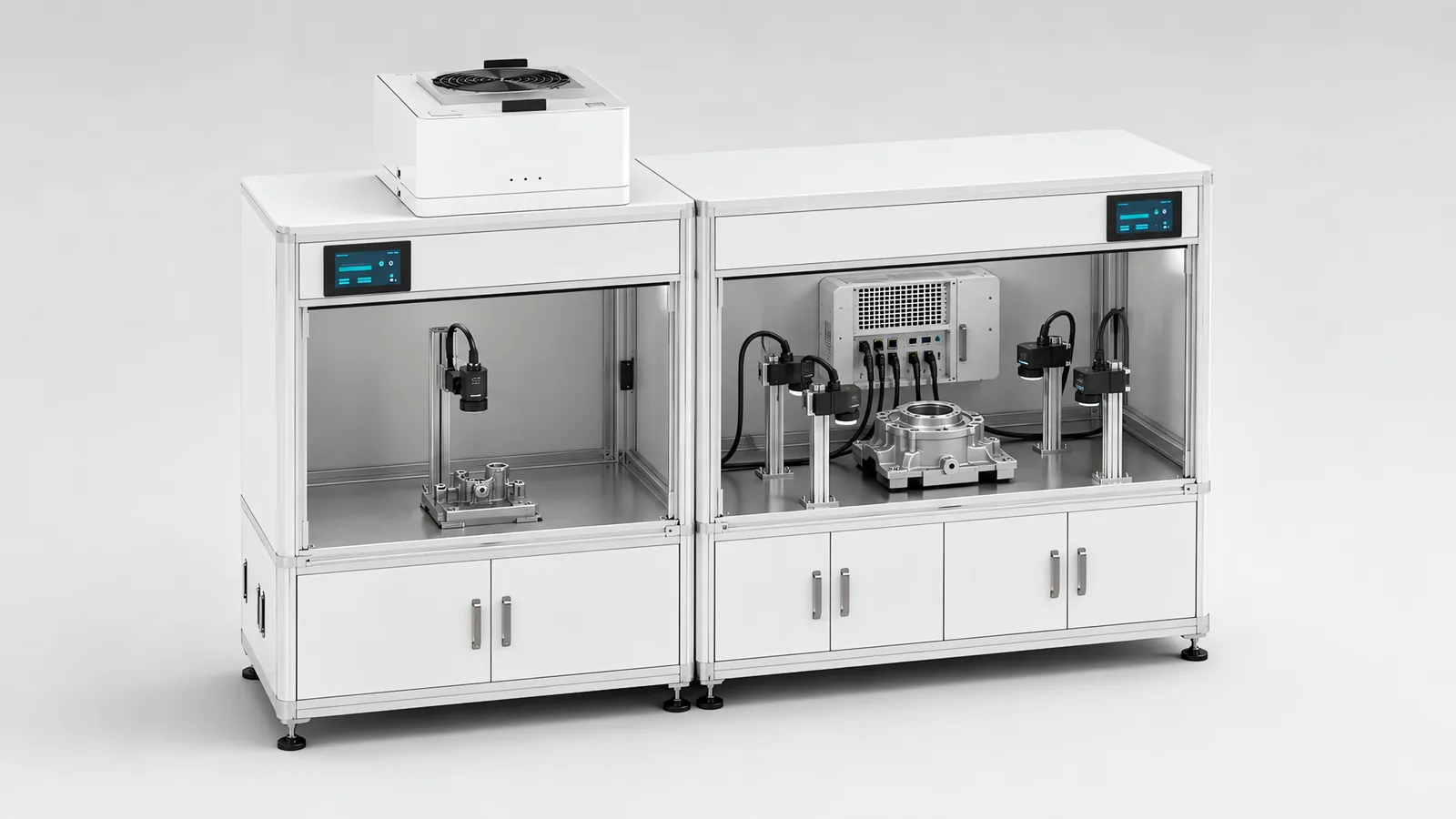
Choose between a smart camera, dedicated vision controller and PC-based vision by the complete inspection task: number of views, processing tools, timing, recipe coordination and maintenance. A self-contained camera can simplify a single inspection gate. A shared controller or PC can suit several views, coordinated measurements or custom software. Image retention is a separate export and storage requirement; it does not automatically require PC-based image processing. Motionwell specifies these architectures for production machines in Singapore, including panel assembly and rotary assembly design.
Machines are designed, assembled and tested at our Woodlands Link facility, and the company has delivered more than 150 special purpose machines since 2014 under ISO 9001:2015 and bizSAFE Level 3.
The short version comes first. The camera is not the unit of comparison. Compare the finished station, because a self-contained smart camera carries a processor per camera, so a job needing three views buys three processors, three device configurations and three recipe sets, and that can lose to one controller or one PC driving three heads from a single trigger and a single calibration. Then compare the decade after handover, because the two architectures ask very different things of the owner over that decade: a swapped body and a reloaded recipe against a drive image, a licence and a software version somebody kept current.
Our delivered systems use configured vendor vision tools, integrated with the fixture, lighting, trigger, PLC handshake, reject device and inspection record. Platform selection follows trials on the customer’s parts, with processing time, detection performance and maintenance considered together. Camera and lighting selection, the optics arithmetic and the false-reject trade-off are on our machine vision inspection capability page.
What Are You Actually Choosing Between?
Three things here, and the middle option is often left off a shortlist framed as a binary. A self-contained smart camera puts the sensor, the optics, often the illumination and the processor in one body at the station. The Keyence IV3 is a representative unit of the class: built-in lighting, fast setup, self-contained, suited to presence and absence, orientation and simple pass or fail at a single point. It is a sensor with a verdict on its output.
A dedicated vision controller puts the processing in the cabinet and the camera heads at the stations. Several heads share one processor, one tool library and one project, which suits multi-point inspection, fast lines and pattern matching, and it is the architecture behind our own multi-station inspection work. It is where many real machines land, and it is the option most often missing from a shortlist written as camera against PC.
A general-purpose PC-based system runs vendor or third-party software on an industrial PC against standard cameras. Where an application needs non-standard optics or an existing in-house image-processing stack, a generic GigE Vision camera with third-party software is that alternative architecture. It buys flexibility and costs the integrated toolchain, the vendor support path, and usually several weeks of development.
| Architecture question | Self-contained smart camera | Dedicated vision controller | General-purpose PC |
|---|---|---|---|
| Camera heads per processing unit | One | Several on one controller | Several, limited by bandwidth and CPU |
| Where the recipe lives | On the device, portable with the body | On the controller, keyed to head positions | On a disk, inside an operating system |
| What a spare part is | A second body plus a stored recipe | A controller and the heads it was calibrated with | An image, a licence and a software version |
| Adding a fourth view | A fourth device, drop and recipe set | Another head on the controller | Another camera on the PC |
| What growth costs | Replacement, because the processor is fixed | A controller class change if the tool budget runs out | Software, and possibly nothing else |
| Toolchain | Vendor GUI, bounded and supported | Vendor engineering software, wider than the GUI and still bounded | Whatever you chose, supported by whoever wrote it |
Read the last two rows together: the bounded toolchain makes a smart camera maintainable by a plant technician, and the same property stops it doing what the vendor did not anticipate.
Why Does the Cost Comparison Only Mean Anything at System Level?
The camera is the cheap part, and what ends up on the invoice is a station. Our published cost drivers are camera count and resolution, lighting complexity, whether the parts can be presented repeatably, and the scope of PLC and MES integration, with a single smart camera checking presence and orientation at the entry level and a multi-camera measurement station with custom optics and full line integration costing several times more. Every one of those is architecture-neutral: the light does not get cheaper because the processor moved into the camera body, and the fixture still has to be designed and machined either way. What the architecture changes is which items multiply when the station needs a second and third view.
| Item on a three-view station | Three smart cameras | One controller, three heads | One PC, three cameras |
|---|---|---|---|
| Processors bought | Three | One | One |
| Software projects and recipe sets to keep in step | Three | One | One |
| Network drops and PLC connections | Three, each handshaking separately | One | One |
| Lighting, lens, mounting, fixture and presentation | Unchanged by architecture | Unchanged | Unchanged |
| Shared coordinate frame between views | Built in the PLC or the robot | Native to the controller project | Native to the software project |
| Cabinet load | Low power, low heat, out at the stations | Controller in the cabinet | PC, storage, UPS and thermal load |
Recipe coordination matters when several stations share product variants. The SCARA panel line links robot paths, grip settings and vision parameters to the selected product; the case study shows that process. Compare how each architecture distributes and verifies recipe versions, then assess the stations affected by one device failure and the procedure for restoring them.
How Much Processing Headroom Do You Need?
You need enough for the algorithm you will have in year three, and the way to estimate that is not to guess at CPU load. Two constraints set the ceiling, and only one is processing. The first is optical, settled before any processor is chosen: resolution at the part is field of view width divided by sensor width in pixels, and you need roughly three pixels across the smallest feature for reliable detection and five or more to measure it. On our own published sizing table, a 20-megapixel sensor across a 400 mm field gives 0.073 mm per pixel, about 1.4 pixels across a 0.1 mm feature, and no processor recovers that. The answers are splitting the field between cameras, indexing the part in several positions, or line scan and motion. The arithmetic is in our vision inspection guide for electronics.
The second constraint is the inspection budget inside the cycle. Measure the complete routine with representative samples, image export and communication enabled. Record the available decision window and remaining margin, then test any planned additional inspection tools against that budget.
Growth after commissioning is not hypothetical, and only some of it is solved by a faster processor. A new defect class appears because a supplier changed a surface finish, costing processing time and, on a validated line, a change control. A defect starts to resist description, so rule-based tools give way to a trained classifier, and that is a step change in processing demand. Somebody asks the camera that checks presence to also report a dimension, which needs more pixels and often a different lens, so it is an optical change, as set out on our inline dimensional measurement page. Or archiving gets added, which is a storage question belonging at design stage, covered on our surface defect inspection page. Ask which of those four is plausible in three years. If none is, headroom you paid for is money spent on a future that did not arrive.
The processing platform still needs usable images delivered on time. Review camera acquisition and bandwidth alongside the smart-camera or PC architecture.
What Changes When Several Cameras Have to See One Part?
Two things change that a per-camera comparison never shows: when the images were taken relative to each other, and what coordinate frame they are reported in.
Synchronisation. One trigger firing several heads means the views are of the same instant, which matters whenever the part is moving, whenever light from one station can reach another, and whenever the verdict combines views instead of collecting independent ones. Three self-contained cameras triggered separately from the PLC can be made to work, but everything downstream inherits the trigger’s jitter, and there are three trigger paths.
Shared calibration. Two cameras reporting positions in their own frames give two numbers that cannot be combined until something relates the frames. Inside one controller or one software project that relationship is part of the project. Across independent devices it has to be built elsewhere, normally in the PLC or the robot program, and maintained by whoever owns that code. That is not an argument that the distributed version fails, only that the work exists and belongs to somebody. Interfaces where two suppliers each assumed the other owned it are a common failure point on these stations.
Calibration discipline matters more when the vision result drives motion. Camera-to-robot calibration is done as a multi-point calibration with verification runs, so accuracy holds across the whole working envelope, and not only at the calibration point. Put that in the specification, because a single-point calibration passes a demonstration and fails an envelope.
A shared frame also ages badly, because a bracket holding a camera can drift and several cameras sharing a frame go subtly wrong everywhere. The defence is a re-verification routine an operator can run on shift against a known artefact.
Platform selection also needs an installed data route. Check vision cabling and link tests with the intended host, camera and operating rate.
Where Is the Reject Decision Made, and How Long Does It Take?
In a PLC-controlled inspection station, the PLC normally owns sequencing and reject actuation, while the vision system processes images and returns results. Safety functions belong to the designated safety control system. Other control architectures are possible; the Industrial PC vs PLC guide sets out the runtime and responsibility choices. In this PLC-and-vision arrangement, a sensor, encoder pulse or PLC output triggers the camera, a light fires, software runs its tools, and the result goes to the PLC over EtherNet/IP, PROFINET or digital I/O.
Build the timing budget from exposure, image transfer, processing, result communication and the remaining travel to the reject point. For example, a target of 150 units per minute gives 400 ms between units; that is a design example, and the available decision window depends on conveyor pitch and reject distance. Test the full inspection routine on representative good and defective samples, including image saving and communication load.
What follows the verdict causes failures that processing time never touches, and none of it depends on where the processor sits: carrying each result along with its part to the reject point, and proving the part actually left the line. Both are covered on our machine vision inspection capability page.
What Happens When It Fails, and Who Puts It Back?
This is where the two architectures differ in a way that shows up on a night shift, and it is a part often left out of the costing. When a smart camera or a vision controller dies at 2 a.m., a technician swaps the body and reloads a stored recipe. When a PC-based system dies, someone needs the drive image, the licence and the right software version, and each of those has to exist, be current and be findable by whoever is on shift. Each also rots quietly: an image taken at commissioning does not contain the recipe changes made since, a licence bound to hardware may not activate on a replacement, and a software version two releases behind may no longer be downloadable.
Backup and restore of the program and the data, and power-loss recovery testing that pulls the supply mid-cycle to prove the machine restarts in a defined, safe state without corrupting the record, are both operational qualification items on the regulated machines we deliver, and both are worth running against the vision architecture. Four questions settle it at design stage: who holds the image, how often it is refreshed after a recipe change, where the licence lives, and how the restored station is proven correct.
A smart camera is not immune to any of this. Its recipe still has to be stored somewhere that is not the device, its firmware version recorded, and a replacement body re-verified before it is trusted. The difference is one of degree and of who can do it, and the degree is large enough to decide projects.
What Does a General-Purpose Operating System Cost in a Validated Plant?
It costs a qualification burden that has nothing to do with inspecting your part, which is why architecture is a regulatory decision on a validated line before it is a technical one. GAMP 5 sorts software by how much of it was written for you, because that is what decides how much you have to test.
| GAMP category | What it covers | Where the architectures land |
|---|---|---|
| Category 1, infrastructure | Operating systems, database engines, runtime firmware | Windows on a vision PC, alongside PLC firmware and any SQL engine behind the data log |
| Category 3, non-configured | Products used as installed, default settings only | A code reader running a stock read job |
| Category 4, configured | Commercial packages configured without new code | A configured vision toolset, on a smart camera or a controller |
| Category 5, custom | Software written for one application and running nowhere else | Bespoke inspection scripts, and the PLC application code either way |
The consequence is direct. A configured vendor toolset is Category 4, and supplier documentation can carry a good share of that burden where the supplier’s quality system has been assessed. Bespoke inspection scripts are Category 5, and nothing carries that burden except your own testing. On top of it, a PC brings a Category 1 operating system with an account lifecycle, a patching policy and an end-of-support date attached.
Patching turns that into a running cost. The mechanism that works is impact-scoped change control: for each patch, record what it modifies, whether anything it modifies is covered by a qualification test, and what verification closes the gap. Operating system and driver patches on an HMI PC usually touch no qualified function and need documented verification only, while changes to control logic, recipe handling or electronic records require the affected tests re-executed. That process is manageable, and it exists only because there is a general-purpose operating system in the machine at all.
Where the result is part of a regulated record, 21 CFR Part 11 applies regardless of architecture, and clause 11.10(h) asks for device checks on the validity of the data source: the record should carry which device produced the reading and whether it was in calibration at the time. What that asks of a PLC and an HMI is on our 21 CFR Part 11 for production equipment page, and the qualification route is on the computer system validation page. A vision PC is also another general-purpose device on the machine network, which puts it inside the zone and conduit design, as our note on IEC 62443 for machine builders explains.
What Do the Two Architectures Do to the Cabinet?
They put the heat in different places, and one of those places is easier to cool. Distributed smart cameras are low power and low heat, and what heat there is sits out at the stations. A PC adds the PC, its storage, a UPS if the record has to survive a power dip, and the thermal load of all three, so enclosure cooling has to be sized for it, and every cooling method is itself a maintenance item: a filtered fan is a filter to change, an enclosure cooler is a unit that fails quietly while the machine keeps running. Have that conversation at cabinet layout.
Ingress is the mirror image. Processing hardware inside an enclosure inherits the enclosure’s rating, while a smart camera sits in the process environment and carries its own. Be precise about what a rating covers, and set it from the cleaning routine: an IP65 enclosure covers dust ingress and low-pressure water jets, so hose-down sanitation between shifts is fine. IP65 is not a high-pressure or steam-cleaning rating, and a sanitation procedure using high-pressure jets or caustic foam belongs on the specification before the station is drawn. Ask the same question of the camera, the window, the light and the cable glands separately, because a housing rated for the wash does not help if the cable entry is not.
Which One Ages Better?
Neither, and they fail differently, which is the useful part. A smart camera or a controller is a vendor product on a vendor lifecycle: the body gets superseded, the replacement is not the same part number, and a recipe exported five years ago may need a software version you no longer have. The mitigation is boring and effective. Store the recipe outside the device, record the firmware version in the handover pack, and buy the spare body while the model is current.
A PC ages on two clocks, the hardware and the operating system, and the second usually runs out first. Ask for the end-of-support date in writing, because that is the number that determines your real patching horizon and the number that turns into a project three years later. We see the far end of this cycle constantly: control-system retrofit is our largest project line in 2026, replacing obsolete PLCs, drives and VFDs on legacy machines, and much of that work has a compliance driver. The machine still runs fine; its controller cannot hold a user account. The same two clocks run on a vision PC, and the operating system clock is the one to ask about in writing.
When Is a PC-Based System Over-Engineering for the Job?
Often it is, and seven situations mark the cases where a self-contained device is the right answer.
One view, one decision, one cycle. Presence and absence, orientation, a code read, a label check, a measurement at a single point. A self-contained unit with built-in lighting does this and a second processor buys nothing. On a multi-station rotary assembly dial, for example, a single-view gate at one station would be rule-based contour recognition with OK/NG sorting to a reject bin on a self-contained unit, because there is one view, one verdict, and a cycle of several seconds to make it in.
Nobody has named who reads the archived images. Full-resolution archiving is a real requirement in some plants and a reflex in others. Three questions need answers before it drives the architecture: who reviews the images, how long they are retained, and what a stored image would prove. Those answers size the export and storage system; they do not by themselves require PC-based image processing.
The plant has no software person, and will not have one. A trained technician can adjust a vendor GUI. A PC-based system needs somebody who writes software, and if that person is not on your site, the station’s response time is somebody else’s travel schedule.
The defect is describable. Rule-based tools are auditable: a threshold on a blob area or a contrast score can be read off, explained to your customer and re-tested on demand. Buying a general-purpose platform for a classifier you do not need trades a supported toolchain for unused flexibility.
You want AI, and assume that means a PC. It does not. Trained defect classification is available inside smart-camera-class devices, so the classifier decision and the operating-system decision are separate ones and should be taken separately. Bundling them buys a patching policy and an account lifecycle you did not need in order to get a tool you could have had in a sealed body.
The line is validated and the inspection is not a critical record. A general-purpose operating system brings Category 1 infrastructure, an account lifecycle and a patching policy into the qualification scope. Carrying that for a presence check is cost with no matching benefit.
The cabinet is full, or the environment is wet. A PC needs enclosure volume, cooling and a power strategy, and where none exists, distributing the processing to the stations is the smaller change.
When Is a Smart Camera Not Enough?
Four situations run the argument the other way.
Resolution outruns the sensor. If the defect size and the field of view do not leave three pixels across the feature, the station cannot work, and the fix is more cameras, indexed positions or line scan.
Several cameras must see one part in the same instant. One trigger, one calibration, one project, and building that across independent devices is work somebody has to own.
Image export exceeds the device’s capacity. First check whether the smart camera or dedicated controller can export every required image while maintaining inspection timing, then size network bandwidth, buffering and server storage. A PC can simplify centralized processing and archiving when those demands exceed the selected device, but image retention alone does not determine the architecture.
The task cannot be expressed in the vendor toolset: a classification problem the toolset cannot describe, an unusual optical arrangement, or an in-house image-processing stack the plant already owns and validates. That is the case for a generic GigE Vision camera with third-party software, bought knowing what it costs. The same goes for growth you can already name, because headroom you can point at is worth buying and headroom nobody can describe usually is not.
Who Has to Maintain It After Handover?
This decides more than people expect, and it often gets asked last when it belongs in the first meeting. The question has three parts and only the first appears on a datasheet: who adjusts a threshold when the reject rate climbs on a night shift, who restores the station after a hardware failure, and who owns the change when the product changes. On a smart camera or a controller those can be the same trained technician in a vendor GUI. On a PC-based system the first might be, the second usually is not, and the third almost never is.
The handover pack has to match whichever answer you chose. Alongside the drawings, schematics and PLC program documentation that ship with every machine, a vision station needs the exported recipe stored outside the device, the firmware and software versions, the licence location if there is one, the calibration artefact and the routine for using it, and a written restore procedure somebody has executed once. Our own integrator selection checklist sets the bar for support at critical spare parts stocked locally or available within 3 to 5 business days, and the wider list of questions worth asking any vendor, including us, is in our guide to choosing an automation system integrator.
Which Should You Specify?
Run these in order. The first that gives a hard answer usually settles it, and where two disagree, the dedicated vision controller is normally the right middle.
- How many views does one part need, and must they be simultaneous? One view is a smart camera question. Several simultaneous views with a shared frame is a controller or PC question.
- What is the smallest feature, across what field of view? Work the pixels first, because an optical shortfall is not recoverable by any processor, whatever the architecture.
- What is the measured routine time against the cycle you have? State the headroom as a number in the specification.
- Does an image of every part have to be kept, and who retrieves it? Set the image rate, file size and retention period, then check camera/controller export, network bandwidth and external storage together.
- Can you describe the defect, or only show examples of it? Only-show-examples points at a classifier, which does not by itself mean a PC.
- Is the line validated, and is the result a regulated record? A general-purpose operating system carries a qualification and patching burden a configured toolset does not.
- Who is in front of it at 2 a.m., and what are they allowed to do? If the answer is a plant technician with a vendor GUI, design for that person.
| Your situation | Start from | Why |
|---|---|---|
| One view: presence, orientation or a code read | Self-contained smart camera | A processor per camera is not wasted when there is one camera |
| Several views of one part, one shared coordinate frame | Vision controller with multiple heads | One trigger, one calibration, one project to version-control |
| Under three pixels across the feature at your field of view | More cameras, indexed positions or line scan | No architecture recovers an optical shortfall |
| Archived image of every part, with a named reader and retention period | Verify camera/controller image export first | Size bandwidth, buffering and external storage; compare PC-based processing when the device cannot meet the combined inspection and export load |
| Non-standard optics, or an in-house image-processing stack | PC-based with generic cameras | Flexibility is what you buy, and it costs the vendor toolchain |
| Validated line, inspection result is a regulated record | Configured toolset on a camera or controller | Category 4 against Category 5 plus a Category 1 operating system |
| No software support on site, and none planned | Smart camera or controller | The maintenance story is the specification |
A mixed answer usually means one station needs an architecture the rest of the machine does not. Mixing them is allowed, provided somebody owns the boundary: which device holds which recipe, and which frame the numbers are reported in.
Frequently Asked Questions
Is a smart camera cheaper than a PC-based vision system?
Per camera, usually. Per station the answer is unreliable, and the station is what you are buying. A self-contained unit carries its own processor, so a job needing three views buys three processors, three sets of vendor software, three network drops and three recipe sets to keep in step. One vision controller with three camera heads, or one PC with three cameras, buys the processing once and shares it. Our own published cost drivers are camera count and resolution, lighting complexity, whether the parts present repeatably, and the scope of PLC and MES integration. None of those four changes because the processor moved into the camera body.
What happens to a PC-based vision system when it fails at two in the morning?
That depends entirely on what was prepared before it failed, which is the strongest argument for the smart camera. A dead smart camera is a body swap and a stored recipe. A dead PC-based system is a drive image, a licence and a software version, each of which has to exist, be current, and be findable by whoever is on shift at the time. So settle three things at design stage: who holds the image, how often it is refreshed after a recipe change, and how the restored machine is proven correct before it runs product again.
Do I need a PC to run AI or deep learning inspection?
Not necessarily, and that assumption drives a lot of unnecessary architecture. Trained defect classification now runs on smart-camera-class hardware as readily as on a PC, so choosing a classifier and choosing a general-purpose operating system are two separate decisions that arrive bundled on most shortlists. The prior question is whether you need a classifier at all: rule-based tools work when you can describe the defect, and a classifier earns its place when you can only show examples of it. A classifier also carries costs a threshold does not, including a defect image library you have to own and store, and a revalidation on every retrain.