
What Problem Does a Vision-guided SCARA Line Solve?
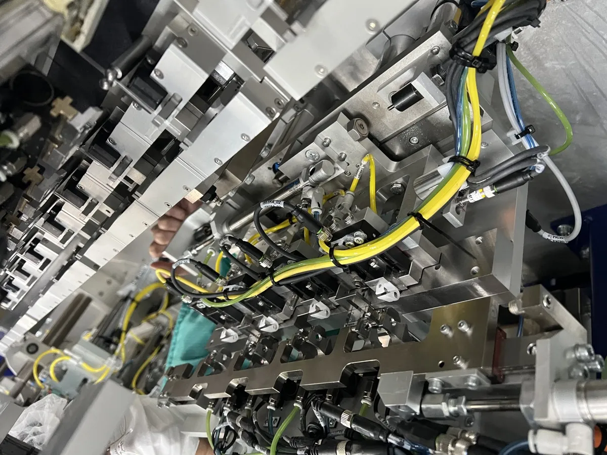
Motionwell Automation designed and built a SCARA robot assembly line for a global industrial sensor manufacturer. The line assembles sensor panels with vision-guided component placement, supporting high-mix production with minimal changeover time.
High mix is the constraint that shapes everything else here. A line running one product can be built around hard tooling: a nest per part, a fixture per station, and mechanical stops doing the locating. Fifteen-plus variants make that arithmetic impossible, so the locating job moves from steel into the camera, and the line’s flexibility becomes a property of the recipe layer. Why SCARA over a six-axis arm for this class of work is covered in our note on SCARA robots in electronics assembly.
How Is the Line Put Together?
SCARA Robot Selection
The assembly line centres on 4-axis SCARA units in the 6 kg payload class. A six-axis arm would reach the same points, but the two wrist axes it adds are orientations that flat-panel placement never uses, and they cost rigidity, cycle time and calibration effort to keep. The class was selected for this application based on:
- Pick-and-place paths coordinated with the available station dwell
- Vision-corrected placement checked against the panel’s contact-alignment tolerance
- A compact body allowing tight station-to-station spacing on the line
- Robot controllers sequenced by the cell PLC over fieldbus, because a per-cycle vision offset is three numbers
Each robot station handles a specific assembly step, meaning connector insertion, adhesive application or component placement, with dedicated vacuum grippers and pneumatic actuators sized for the part geometry. Grippers are per station: one gripper covering every component on the panel would have to be sized for the largest part, and it would then mark or drop the smallest.
Vision System
Each assembly station carries a 2-megapixel camera on an industrial vision controller. Resolution follows the smallest feature that has to be measured, never the largest sensor available, because every extra pixel costs acquisition and processing time inside a cycle whose inspection budget is fixed by the robot placement time. The vision system provides:
- Pre-placement location checks against calibrated image coordinates
- Post-placement quality inspection confirming component seating depth and angular alignment
- Component presence and orientation detection using pattern matching and edge detection algorithms
- Barcode and 2D DataMatrix reading at the station, so a panel that fails an inspection is already tied to its serial number when it is rejected
Inspection timing is checked as part of the station cycle, including exposure, processing and result transfer. Lighting and fixtures keep the target within a stable search window so the routine can make a repeatable decision. The relationship between optics, contrast and algorithm choice is explained on our machine vision inspection capability page, with application examples in the machine vision inspection guide.
Recipe Management and Tray Handling
The PLC recipe system coordinates the settings for each panel variant:
- One-touch changeover between panel variants from the line HMI, with recipes selected by name
- Automatic adjustment of robot paths, vacuum grip profiles, and vision inspection parameters
- Production tracking by variant and batch with data logged to CSV for MES integration
- Quality data segregation by product type with automatic SPC charting
Incoming components arrive in JEDEC-standard trays loaded into gravity-fed tray magazines. The SCARA robot picks components from the tray grid pattern, and empty trays are automatically stacked and ejected to a return conveyor. Tray changeover is tool-free, using quick-change nest plates for different component tray formats.
How Does the Line Hold Placement Accuracy Across Variants?
SCARA Robot Specifications
The assembly line uses 4-axis SCARA robots (X-Y-Z-R configuration) for high-speed component placement. Payload class is sized on the gripper and the part together, because a heavier end effector is what pulls the achievable speed down at a given accuracy. The four axes provide horizontal reach (X-Y), vertical stroke (Z), and rotational alignment (R), which is the kinematic match for pick-and-place operations on a flat panel surface.
Key specifications:
| Parameter | Specification |
|---|---|
| Axes | 4 (X-Y-Z-R) |
| Placement verification | Measured on representative panels with vision, fixture and tooling in the loop |
| Cycle verification | Complete pick, correction, placement and inspection sequence |
| Payload selection | Combined gripper and component load over the operating reach |
The acceptance criterion is contact alignment on the assembled panel. Robot repeatability, camera calibration, fixture stability and tool compliance contribute to that result, so the complete station is tested across the selected panel variants.
Dome Light Illumination System
The vision inspection stations use dome lights (hemispherical diffuse illumination) positioned above the inspection field. Dome lighting provides shadow-free illumination by surrounding the part with diffused light from all angles simultaneously. This elimination of shadows is essential for:
- Accurate edge detection on components with complex geometries, where directional lighting would create shadow artifacts that interfere with dimensional measurement algorithms
- Consistent inspection of reflective metallic surfaces (connector pins, solder joints) that produce specular glare under ring lights or bar lights
- Reliable detection of surface contamination and foreign material, which requires uniform illumination to distinguish genuine defects from lighting artifacts
The dome lights use white LED arrays with diffuser panels at a neutral colour temperature, providing stable, repeatable illumination conditions independent of ambient light changes in the production area.
Vacuum End-Effector and XYZ Linear Modules
Panel alignment at the assembly stations uses a combination of vacuum end-effectors and XYZ linear modules:
- Vacuum end-effector: Vacuum cups with adjustable suction force grip the panel surface without mechanical clamping marks. Vacuum level is monitored by a pressure sensor to confirm grip before the robot initiates movement.
- XYZ linear modules: Motorized linear stages on each axis provide fine positioning with micrometer resolution for panel alignment against reference datums. The linear modules compensate for panel dimensional variations (warpage, edge trim tolerance) that would otherwise cause positional error at downstream assembly stations.
The combination allows the system to handle panels of varying thickness and flatness without dedicated fixtures for each panel variant.
Electric Screwdriver with Torque Control
Selected assembly stations integrate torque-controlled electric screwdrivers for fastening sensor modules to the panel substrate:
- Target torque is set per fastener type in the recipe, against a window agreed with the customer for that joint
- The PLC records the fastening result for every fastener, logged against the panel serial number
- Fasteners that fall outside the torque window trigger an immediate reject, preventing undertightened assemblies, which risk loosening in service, and overtightened ones, which risk stripped threads or a cracked substrate
Real-Time Vision Deviation Compensation
The vision system performs real-time deviation compensation on every pick-and-place cycle using a three-step process:
- Image acquisition: The camera captures an image of the target placement location on the panel
- Position and angle calculation: The vision software identifies fiducial marks or component edges in the image, calculates the X-Y position offset and angular deviation (theta) between the actual panel position and the programmed nominal position
- Compensation data transmission: The calculated X, Y, and theta offsets are sent to the SCARA robot controller via high-speed fieldbus communication. The robot adjusts its placement trajectory in real-time to compensate for the measured deviation
The compensation cycle corrects the measured offset within the calibrated operating range. Test samples cover the expected panel and tray-position variation, and the controller holds the cycle if the target cannot be located or the correction exceeds its allowed window.
Blue Polycarbonate Safety Enclosure
Blue-tinted polycarbonate panels allow operators to observe the assembly process through the enclosure. Panel material, thickness, mounting and access arrangements are selected for the hazards identified in the cell risk assessment. Visibility and glare are reviewed with the internal inspection lighting operating.
Access doors in the enclosure use safety-rated interlocks that halt robot motion when opened. Interlock selection, performance level and the supporting test evidence are handled as part of our machine safety and compliance work. The enclosure is also the controlled environment boundary, reducing airborne dust and fibre contamination on the sensor panels during assembly.
Which Five Decisions Shaped This Line, and What Did Each Cost?
Combining fixture location with vision correction. The fixture holds the panel stable while vision measures its residual offset. This supports related variants without requiring every locating feature to carry the full placement tolerance. Fiducial condition and the allowed correction window are checked before the robot moves.
Recipe and tooling changeover planned together. Robot paths, grip settings and inspection parameters are selected from the HMI. The variant matrix identifies any physical tool changes and the first-piece checks after them. That gives the operator one complete changeover procedure.
Vacuum end-effectors. Vacuum grips the panel face without leaving clamp marks on a cosmetic surface, and grip is confirmed by a pressure sensor before the robot moves. It constrains what the line can handle: perforated, heavily textured or warped panels present a poor sealing surface, which is why the XYZ linear stages sit underneath to reference the panel against hard datums before the placement runs.
Dome lighting. Dome heads take vertical space directly above each inspection field, which limits how a gripper can approach that station and adds to the height of the enclosure. They were chosen anyway because connector pins and solder joints throw specular glare under directional light, and a highlight sitting on an edge reads as a dimensional deviation to the measurement algorithm.
A blue-tinted enclosure instead of sheet metal. Sheet metal is cheaper and blocks light entirely; clear polycarbonate gives the best view. The tint was chosen to cut glare from the internal LED and dome lighting for operators working alongside the line for a full shift, at the cost of some visibility into the cell.
Where Else Does This Engineering Show Up?
The recipe-driven architecture on this line reflects our approach to custom special purpose machine design for the electronics and semiconductor industry. Where the stations sit around an indexing dial instead of along a conveyor, the layout trade-offs change, and we set those out in how we design multi-station rotary indexing assembly machines.