
Why Is Automatic Test Equipment Useful for Connector Force Testing in a Cleanroom?
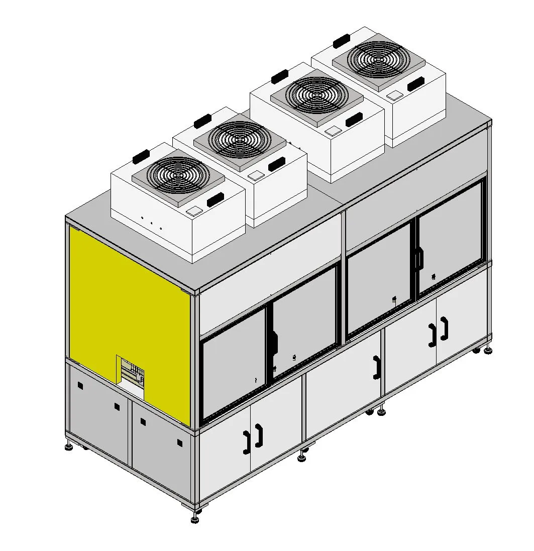
Motionwell delivered a series of automatic test equipment (ATE) machines for electronics manufacturers in Singapore. Enclosed, FFU-filtered test stations perform mechanical and electrical checks on connectors, components and sensors in cleanroom production applications.
Manual insertion-force testing can introduce variation in approach angle, insertion rate and specimen alignment between operators. Automated handling controls these inputs through the fixture and test sequence. A measurement-system study then evaluates repeatability and reproducibility, including operator, fixture and instrument effects, before results are combined for capability analysis. Keeping the transfer inside an FFU-filtered enclosure also reduces handling between test steps. The layout, airflow and test access are developed together, as described in our cleanroom automation guide.
Automated test equipment sits alongside the rest of Motionwell’s laboratory and test automation work, which covers sample handling, instrument integration and result capture for regulated environments.
How Is the ATE Built for ISO Class 7/8?
Cleanroom Integration
The cleanroom ATE variants use enclosed test zones with fan filter units. The design addresses:
- HEPA-filtered air circulation within the test enclosure
- Airflow and pressure management around loading openings and test stations
- Material selection compatible with cleanroom protocols
- Easy-clean surfaces for routine maintenance
Multi-Station Test Architecture
The ATE uses a circular transfer system with multiple test stations:
- Automated component loading via collaborative robot
- Sequential test execution across stations
- Real-time pressure and displacement monitoring
- Automated pass/fail sorting based on test limits
- Data logging in SPC-ready format
Cobot Loading System
A collaborative robot handles automatic loading and unloading of test specimens:
- Tray-based batch loading for high throughput
- Vision-guided pick-and-place for precise positioning
- Dual tray arrangement with replenishment coordinated with loading and testing
- Automatic sorting of tested parts by result
The loading-cell risk assessment considers the robot, gripper, specimen, fixtures and enclosure openings together. The selected collaborative operating mode and safeguarding arrangement follow the tasks people perform during tray replenishment, production, cleaning and recovery. Where required, access protection combines guarding, interlocks or presence sensing with the robot’s safety functions. The contact points and stopping behaviour of the complete application are then verified. Our guide to cobot safety standards explains this application-level approach.
What Are the Headline Machine Specifications?
| Parameter | Specification |
|---|---|
| Cleanroom design | FFU-filtered enclosure for ISO Class 7/8 production environments |
| Transfer | Multi-station circular |
| Loading | Collaborative robot |
| Control | PLC with machine-mounted HMI |
| Data | SPC-ready logging |
| Tests | Force, fatigue, pressure, electrical |
How Does the Machine Hold Measurement Repeatability over a Long Run?
Positioning and Repeatability
The loading tool and fixture locate the connector before the test stroke. Probe alignment, approach speed and fixture compliance are checked together because each can change the measured insertion-force curve. Acceptance testing measures loading repeatability at the fixture interface using representative parts. Reference checks and recalibration intervals are defined in the maintenance and quality procedures.
Jig and Fixture Materials
Test fixtures and specimen nests use nylon (PA66) and POM (polyoxymethylene/acetal) engineering plastics. The material grade is selected for the contact geometry, test method and production environment:
- Electrical behaviour: Supplier datasheets and the device’s ESD requirements guide the choice of insulating or static-dissipative grades. Fixture contact points, grounding and isolation are checked against the resistance and continuity measurements the station must make.
- Mechanical and environmental performance: Wear, friction, stiffness, dimensional change and compatibility with cleaning agents are evaluated for the selected grade and operating conditions. Reference-specimen checks track the effect of nest wear on alignment and measured results.
Fixture changeover uses located mounting interfaces so the nest can be replaced and checked against a reference specimen. The changeover test includes the swap, recipe selection and approval of the first result.
Pneumatic System Architecture
This machine groups its pneumatic valves on centrally mounted islands, allowing exhaust routing to be coordinated away from the specimen area. Valve location, tube length and diameter, exhaust treatment and the required response time are reviewed together. Stroke timing is verified on the assembled station at its operating pressure.
Magnetic reed switches report the cylinder’s extended and retracted positions to the PLC. These signals confirm actuator travel for the sequence. Connector seating is established by the located fixture and the relevant process signals, such as measured displacement, force or contact state, as defined in the test method. The PLC checks those conditions before advancing to the next measurement and provides a defined recovery path for an incomplete step.
Each valve bank is regulated to the pressure its station requires. Drying and filtration are specified from the incoming air quality, cleanroom application and component requirements. Lubrication is applied only where the selected components require it, with the lubricated circuit and exhaust kept separate from the clean specimen area. Air preparation and exhaust routing are checked as part of the installation and maintenance plan.
SPC Data Export
The PLC logs all test measurements (force, displacement, resistance, continuity) in real-time and exports the data in SPC-ready format. Data can be filtered and exported by:
- Batch number: All test results from a single production batch grouped for statistical analysis
- Serial number: Individual device test history for traceability and warranty tracking
- Test parameter: Specific measurement types isolated for process capability studies (Cp/Cpk calculations)
Measurement acquisition and reporting are separate parts of the architecture. The machine records the result against the specimen and test recipe; CSV exports support offline analysis, while a plant connection can expose agreed values through OPC-UA to SCADA or a historian. The interface specification defines identifiers, units, timestamps, result status and the limits applied to each test so the receiving system can interpret the record consistently.
Authorized users select approved recipes at the HMI. Changes to test acceptance limits or alarm settings follow the agreed access and approval workflow and are recorded with the user, time and recipe version. Statistical control limits used for SPC analysis are managed under the quality procedure, separately from the acceptance limits that determine a specimen’s pass/fail result. Logged pass/fail and cycle records can also support the plant-level metrics described in our explainer on what OEE actually measures.
Circular Belt Transfer with Pallet System
The multi-station test architecture uses a circular belt transfer system with a pallet-based workpiece carrier. Pallets circulate continuously around the loop, stopping at each test station via pneumatic stopper pins. Each pallet carries a single test specimen in a precision nest, maintaining the specimen’s orientation through all test stations.
In this circular layout, pallets return to a shared loading station after completing the test sequence, and the cobot loads and unloads at that position. Buffer positions accommodate differences between station cycles; their capacity is evaluated against the dwell times and required output. Pallet identification uses RFID tags to let the PLC track the specimen’s position and test status throughout the loop.
The equipment class this build belongs to is set out on our automated test equipment and cleanroom automation equipment pages.
The same separation between product behaviour and fixture behaviour is useful when specifying a functional test fixture. For a different test duty involving high-voltage insulation checks, the hipot equipment guide sets out the additional enclosure, connection and result-handling questions.
How Do the Layout, Loading and Fixture Choices Affect the Test Cell?
The design combines four choices, each assessed against the test sequence, product range and available space.
Circular pallet transfer. Returning pallets to a shared load/unload position lets the robot serve the transfer from one handling point. Station spacing, buffer positions and access are planned around the enclosure. Adding a test involves reviewing available space, routing and cycle balance; a linear or hybrid layout offers another way to arrange future stations.
Cobot loading. Programmed picks and tool changes accommodate different specimen presentations. The comparison with a dedicated gantry includes tray access, reach, safeguarding, changeover and the complete pick-to-place cycle. Both architectures can support programmable handling; the application determines the required motion and tooling.
POM and nylon nests. Replaceable polymer contact surfaces provide a way to match fixture geometry and electrical behaviour to the specimen. A metal support structure can supply stiffness while selected contact materials provide the required isolation or ESD behaviour. Material grade, clamping load, cleaning conditions and measured wear establish the inspection and replacement schedule.
Position and process feedback. Cylinder switches give the sequence actuator-state information, while fixture location and test signals establish the specimen’s condition. Sensor selection adds I/O, wiring and diagnostic work, but also provides explicit conditions for advancing, holding and recovering the sequence. Acceptance testing checks these conditions alongside the normal cycle.
Test duration determines how the stations are arranged. Short-cycle mechanical and electrical checks suit the inline transfer. Longer burn-in or conditioning steps can use parallel test positions or an offline rack sized to the required output. Specimen identification links those results back to the same record and directs the part to its next operation or final sort.
Where Else Does This Engineering Show Up?
The same handling, vision and data discipline runs through our work for the electronics and semiconductor industry. The vision-guided handling and inspection logic is described in more depth on our machine vision inspection capability page, and a related high-mix build is documented in the SCARA vision-guided panel assembly case study.
If you are scoping a test cell and want to talk through station count, changeover time and data capture before drawings exist, send us the part and the test spec.