
What Does This Machine Do to a Turbine Blade?
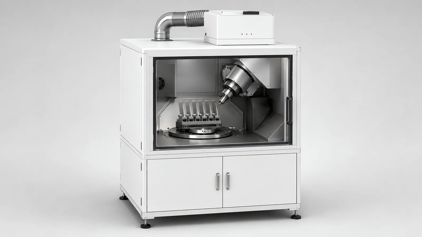
Motionwell Automation designed and built a five-axis CNC shot peening machine for an aerospace turbine blade MRO services provider. The machine is a sealed blast chamber. Inside it a nozzle runs on X, Y and Z linear stages with a B-axis swing of +/-90 degrees, over a C-axis rotary table that turns the blade through 360 degrees continuously. An aluminium quick-change fixture with quick-locking clamps sits on that table. A collaborative arm loads blades through a window from comb-shaped racks that keep stored blades apart. Motion runs as a G-code program on a dedicated motion controller, and never out of ladder logic, because the five axes have to interpolate together for the nozzle to hold an angle through a curve, and an axis that arrives correctly but late has already changed the process. An operator panel at the station runs the program and records what it ran.
What the blade leaves with is a compressive stress layer, and that layer is what delays fatigue crack initiation and growth in the aerofoil. The matte texture on the surface is a by-product of the treatment.
That one fact shapes every station on the machine. A blade peened at the wrong pressure, or with a clamp standing between the nozzle and a fillet, comes out of the chamber looking like a blade peened correctly and goes back into an engine that way. So the machine was not built to produce a finish. It was built to hold a defined set of inputs, to reach every treated surface at a controlled angle, and to leave a record that the run happened the way the process specification says it should have.
| Station | What stands there | What it contributes |
|---|---|---|
| Input rack | Comb-shaped rack shaped to blade geometry, dual-side access | Untreated blades stored without touching each other |
| Loading arm | Collaborative arm working through a window into the chamber | One blade in and one blade out per cycle |
| Blast chamber | Sealed enclosure with wear-resistant liners and a collection trough in the floor | Contains the stream and starts media recovery |
| Nozzle head | X, Y and Z linear stages carrying the nozzle, plus the B swing | Position and standoff, then impact angle |
| Rotary table | C-axis table with an aluminium quick-change fixture | Presents every side of the aerofoil from one clamping |
| Air wash | Air curtain inside the chamber | Blows media off the blade before the door opens |
| Extraction | Separate dust collection enclosure with filter cartridge | Takes airborne fines out of the chamber |
| Control cabinet | Motion controller with the operator panel above it | Interpolates the five axes under G-code and logs the parameters |
| Output rack | Treated-blade rack, with an intermediate rack for two-way flow | Keeps treated and untreated parts physically separate |
The rest of this page walks those stations in the order a blade meets them, starting with the axis that decides the result.
For the process background behind this machine, see how shot peening differs from shot blasting. It explains why cleaning a surface and controlling a peening treatment use different acceptance measures.
Why Does the Nozzle Have to Be Presented to the Blade?
Three axes reach every point on an aerofoil. What three axes cannot do is arrive at each of those points at the same angle.
Media leaves the nozzle as a directed stream, and what it does on landing depends on the angle at which it lands. A blade curves in two directions at once, so a nozzle set square to the surface at one point along the chord is at a glancing angle a short distance further along. Reaching a surface and presenting to a surface are separate requirements, and the second one is what produces an even result across a curved part. This is why the axis count was settled before any structure was drawn, in the way our mechanical design and simulation work treats kinematics generally: a machine cannot be given another degree of freedom afterwards without becoming a different machine.
| Axis | What it moves | Range on this machine | What it buys |
|---|---|---|---|
| X | Nozzle along the blade | Sized to blade length | Traverse |
| Y | Nozzle across the blade | Sized to blade width | Traverse |
| Z | Nozzle height | Sized to blade height | Standoff from the surface |
| B | Nozzle swing | +/-90 degrees | Impact angle onto a curved surface |
| C | Workpiece rotation | 360 degrees continuous | Every side of the aerofoil from one clamping |
Read the last two rows together and the machine’s logic shows. X, Y and Z decide where the nozzle is and how far off the surface it stands. B and C decide what the surface looks like from the nozzle’s point of view, which is the part of the geometry that governs the outcome. The C axis also earns its keep on handling: a blade turned under the nozzle does not have to be unclamped, reversed and re-located halfway through a cycle.
The path is a G-code program. That was a deliberate choice on an audited process. A program can be read, compared against its previous revision, archived beside the part family and reissued to a second machine. A taught path lives inside a controller and inside somebody’s memory.
Which Process Parameters Are Recorded, and Which Are the Machine’s Limits?
The machine carries capability windows. The process carries numbers, and those numbers live inside the windows. On this build the windows came out as follows, and all of them are set per part family at commissioning.
| Parameter | Window on this machine | How it behaves at run time |
|---|---|---|
| Peening pressure | 0.3 to 0.6 MPa | Logged against the blade |
| Media type | Steel shot, ceramic shot or glass bead | Fixed per part family, changed under change control |
| Media size | 0.2 to 1.0 mm | As above, and confirmed after the recovery loop |
| Coverage | Defined by the part’s peening procedure | Verified by the specified surface inspection and exposure method, separately from Almen intensity |
| Cycle time | Set by the coverage specification | An output of the three rows above |
Two rows deserve more than a table cell. Media is often treated as a consumable and it behaves as a process variable: steel shot, ceramic shot and glass bead at the same pressure do not produce the same result, and the 0.2 to 1.0 mm band spans materially different processes at its two ends. Whoever refills the hopper is not the person who gets to choose.
Cycle time follows the nozzle path, travel speed, media delivery and required exposure. Productivity work therefore considers fixturing, loading and path efficiency while retaining the qualified intensity and coverage requirements.
The recipe is released after the specified intensity and coverage checks. The controller then holds the approved parameters and records the settings used for each run, with recipe revisions traceable to the blade family.
How Is a Blade Held Without Spoiling the Root?
Two requirements pull against each other. The blade has to be held rigidly enough that it does not shift under the stream, because a part that moves changes both standoff and impact angle and therefore changes the process. At the same time every surface that has to be treated must stay exposed to a nozzle trying to reach it from several attitudes.
The root is where those two meet. It is the obvious place to clamp and it is also the load-bearing interface into the disc, which makes it the surface least tolerant of a witness mark. Inside the chamber the blade sits in a grid rack built to protect the root, and the process fixture on the C-axis rotary table is an aluminium quick-change unit closed by quick-locking clamps. Quick-change matters here for a reason beyond changeover time: the fixture is a per-family item, so the machine was designed on the assumption that fixtures would be swapped.
Shadowing is the failure mode that looks like a cycle time problem and is not. Anything the fixture puts between the nozzle and the surface leaves a local coverage hole, and because the obstruction turns with the part on the C axis, more time in the chamber does not fill it. On a five-axis machine the fixture therefore becomes part of the path problem: the program has to arrive at each surface from an angle where no clamp is standing in the way. Fixture geometry and program are developed together.
How Does the Collaborative Arm Load the Cell?
The loading duty is one blade in and one blade out against a cycle measured in minutes, from racks a person refills between batches. That duty was matched with a collaborative arm working through a window in the chamber wall, with the application tooling designed in house for a component that is aerodynamic, sometimes coated and unforgiving about where it is touched. The gripping problem is the one described on our end of arm tooling page, applied to a part that has no convenient flat.
The cycle runs in one loop:
- The arm takes an untreated blade from the input rack.
- It seats the blade in the fixture on the rotary table.
- The chamber door closes and locks, and the G-code program runs the five axes over the blade.
- The air wash clears media off the blade before the door is released.
- The arm lifts the treated blade out and places it in the output rack.
- The next blade starts, and the cell continues until the input rack empties or the output rack fills.
The racks carry a second job that is easy to overlook. Untreated and treated blades never share a rack, with an intermediate rack where parts have to flow in both directions, so the state of a blade is a physical fact about where it stands and nobody has to keep a note current. On a process whose result cannot be seen on the part, that is worth more than the handling convenience, and it is the reason the racks are shaped: the comb profile follows blade geometry so stored blades do not touch each other.
Loading and containment are separate states in one coordinated sequence. The loading opening is released only after the blasting process reaches its defined safe state. The robot loads or unloads, withdraws clear, and the opening closes before blasting is enabled. Personnel access doors have their own interlocks and reset conditions. The integrated robot, loading aperture and blast chamber are assessed together through our machine safety and compliance process, with the relevant robot requirements under ISO 10218-1 and ISO 10218-2.
How Is the Media Kept Inside the Machine?
Three streams leave the nozzle and each of them has somewhere it has to go.
Spent media falls to a collection trough in the chamber floor and returns through a recovery loop. Recovery is where a peening machine differs from a cleaning cabinet, because the loop is returning media that has already been fired at a hardened surface. Media that has broken down or changed size is no longer the media the process was qualified on, so how the loop screens what it returns, and what confirms it is doing so, is a specification question. It is also why media size is re-confirmed after recovery.
Airborne dust and fines leave through a dedicated extraction enclosure with a filter cartridge, standing as its own unit beside the machine along with the control cabinet. Siting abrasive dust collection away from the machine is straightforward; keeping that dust out of an enclosure standing next to it is not, which is the same reasoning we apply to control panel design and build in dusty rooms.
The third stream is media riding out on the finished blade, which the air wash removes before the door opens. Without it, media leaves with the part, into the output rack and into the next operation.
The energy in the stream has to be absorbed as well, and it is, by wear-resistant liners on the chamber walls. Those liners are a maintenance item with a service life, and treating them as one keeps the wear from arriving later as an unplanned shutdown.
What makes containment structural on this machine is that the part program switches it. An operator cannot forget to turn on extraction, because extraction is an M-code in the same program as the motion.
| M-code | Function |
|---|---|
| M03 / M05 | Peening on / off |
| M08 / M09 | Air wash on / off |
| M212 / M213 | Dust collector on / off |
| M214 to M217 | Machine lighting and door lock |
What Record Does the Process Leave?
The record is a deliverable of the machine, for the reason set out at the top of this page: nobody can inspect a finished blade for the property that was bought.
Three things make it up. Process parameters are logged by the control system on every run, and never transcribed by an operator at the end of a shift, so each blade carries its own processing record and the record is made by the machine that ran the part. The operator interface shows live X, Y, Z, B and C positions beside the running G-code program list and the M-code function table, so the state of the machine is something an operator reads, which is the design principle behind our HMI and SCADA integration work. And the machine shipped with a documentation package covering maintenance procedures, calibration schedules and operator training materials, assembled to survive a customer audit.
One item belongs in that record that buyers rarely ask for. Because the path is a program, the program identity and its revision are part of the evidence alongside the parameters. A pressure captured against a part number says what the air was doing; the program revision says where the nozzle went. Both are worth holding under the same change control.
Which Four Decisions Shaped This Machine, and What Did Each Cost?
It is a nozzle machine. The whole design premise is a controlled nozzle presented to a specific surface under a program. A centrifugal wheel machine throwing media at bulk parts is a different mechanism answering a different question, and nothing on this page transfers to it.
Unattended means rack-limited. Rack capacity with dual-side access is what sets the length of a run without an operator, so the useful planning figure is blades per rack against blades per shift. Somebody still walks over to refill.
The floor area is larger than the machine envelope. The extraction enclosure, the control cabinet and the input and output racks all stand outside the chamber, so the space the cell asks for is not the space the chamber occupies. Extraction routing is a building service the site has to accept somewhere.
The control stack spans two vendors. The motion controller and the operator panel come from different makers, which is a sound machine and is also two engineering tools, two spares chains and two support routes for whoever owns it in year six. Ask for both toolchains, both project files and both licences at handover, because the half you cannot open is the half that will need the change. That is a decision to take deliberately at platform selection, as we set out on our PLC migration and upgrade page.
Where Else Does This Engineering Show Up?
The wider scope it belongs to, including force-controlled robotic grinding for CFRP composite panels and the nacelle paint removal work developed with A*STAR SIMTech, is on our aerospace and precision engineering page. The machine concept and how a peening cell gets specified are covered on our aerospace surface treatment automation page. Machines like this one are designed, assembled and tested at our Woodlands Link facility, where the company has delivered more than 150 special purpose machines since 2014 under ISO 9001:2015 and bizSAFE Level 3, and how a build of this shape is scoped from concept to commissioning is in our guide to special purpose machine design.
For a different edge-removal task, the deburring machine guide applies the locating and access questions to burr removal and protected features. Its acceptance checks concern residual burrs and excessive removal, distinct from this machine’s peening objective.
To scope a peening cell, send us the blade drawing with the treated and excluded surfaces marked, along with your intensity and coverage specification and how many part families share the process.