
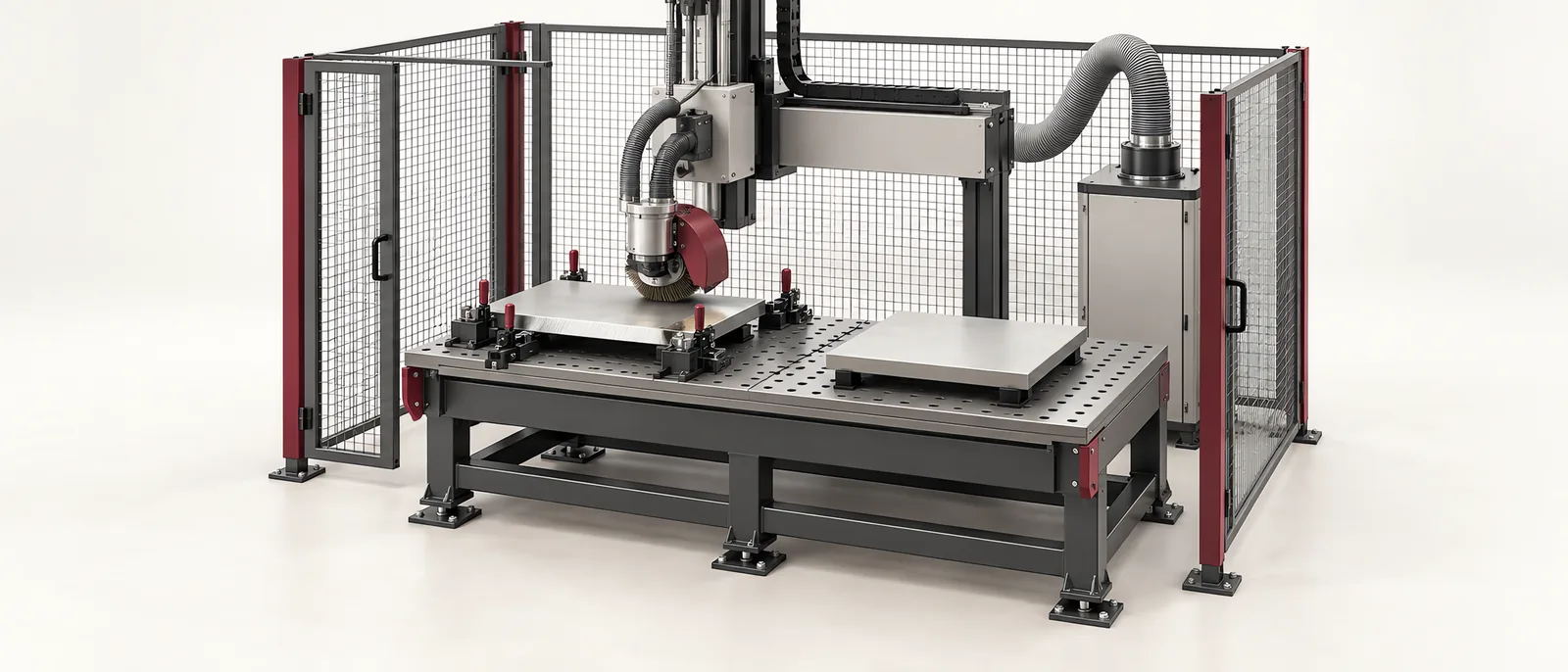
Conceptual equipment illustration.
A deburring machine must remove the unwanted material without damaging the features the part needs to keep. Begin with the burr’s location, attachment and variation, then define the permitted edge condition after processing.
Removing a loose burr, producing a controlled edge radius and improving the broad surface finish are different requirements. A machine may perform several of them, but each result needs its own acceptance check.
Describe the Burr Before Comparing Machines
Record the material, preceding process and the features affected. A thin burr on a laser-cut sheet edge presents a different problem from a burr inside intersecting drilled holes. Include examples from the least favourable normal machining condition.
Mark protected features on the part drawing or inspection image. Threads, sealing faces and sharp functional edges may need to remain unchanged. This makes the acceptable removal boundary visible during process development.
For aerospace and precision manufacturing, connect that boundary to the actual component requirement. A visually smooth part is not enough if a critical edge or dimension has changed.
Match Access to the Process
| Part condition | Process route to investigate | Important limitation to test |
|---|---|---|
| Broad, accessible sheet edges | Conveyor-fed abrasive or brush machine | Part support, edge consistency and protected surfaces |
| Local external burr | Dedicated tool or controlled robotic path | Reach, contact and removal at the exact feature |
| Batch of suitable small parts | A mass-finishing process | Part-to-part contact, media access and dimensional effects |
| Internal or intersecting feature | A method designed for that internal geometry | Access and inspection of the hidden result |
Timesavers’ 42-series description distinguishes deburring, edge rounding and finishing functions within a multi-head machine. Its configuration illustrates one route for suitable parts; it does not establish that the same arrangement can reach every burr.
Support the Part Through Contact
Review how the workpiece is held against the process forces. Small or thin parts may need a dedicated support arrangement. A tool that removes a burr on a rigid trial block can bend a less supported production component.
The mechanical design and simulation scope should include access, contact direction, clamping and the removal of debris. Check loading and tool changes as well as the nominal processing path.
A robotic approach needs the same process development as a dedicated machine. Path repeatability does not automatically compensate for varying burr size, tool wear or part position.
Establish a Removal Window
Run representative samples and compare the remaining burr, edge shape and relevant dimensions. Adjust the process in controlled steps, retaining the setup and inspection results for each trial.
Include the condition of the abrasive or cutting tool. Test how the result changes with use and identify when the tool must be replaced or the process rechecked. A new-tool demonstration alone does not establish the usable production range.
Keep the requirement separate from surface-treatment automation. Our CNC shot-peening machine case study concerns a different process objective, although locating, controlled motion and repeatable presentation are relevant engineering considerations in both.
Inspect Where the Burr Was
Choose an inspection method that can reach and resolve the affected feature. For internal burrs, a view of the external surface does not prove removal. Include cleanliness where residual particles can affect assembly or operation.
Acceptance should cover the difficult permitted burr, the most vulnerable protected feature and the intended tool-use interval. Record both residual defects and excessive removal. This establishes whether the process has a practical operating range between under-processing and damage.