
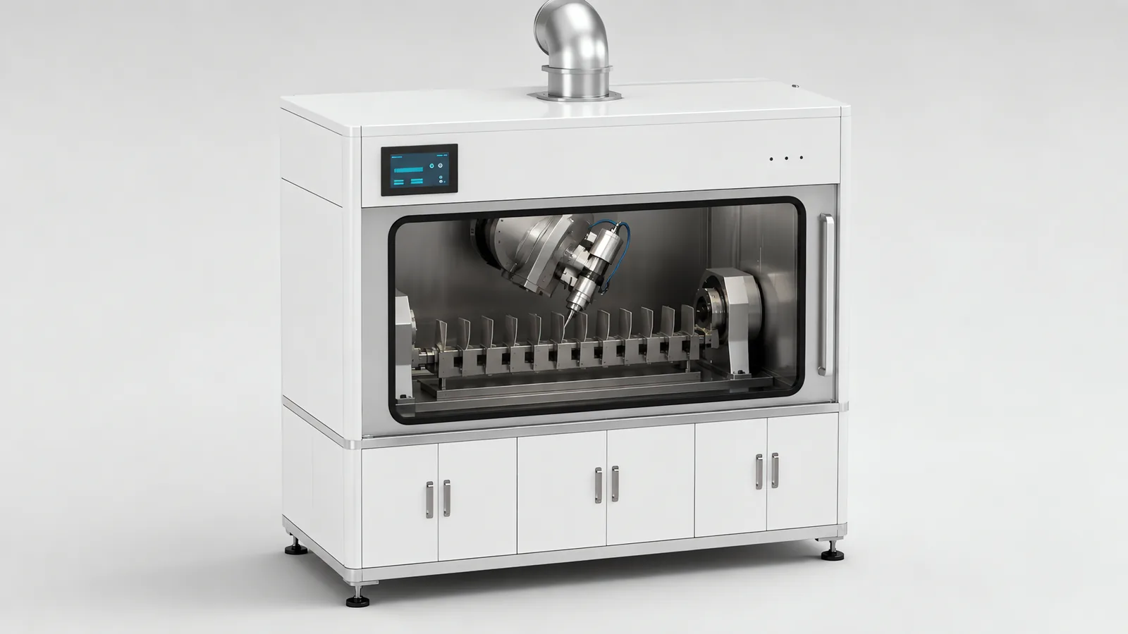
Motionwell Automation builds automated shot peening machines in Singapore for aerospace surface treatment. The machine controls nozzle position, impact angle, media delivery and exposure time against the part’s process specification. Acceptance checks distinguish peening intensity, measured with Almen strips, from coverage on the component surface.
Our delivered turbine blade machine moves X, Y, Z, B and C simultaneously under G-code, works at 0.3 to 0.6 MPa with media between 0.2 and 1.0 mm, and is loaded by a collaborative arm from comb-shaped racks with dual-side access. The build is documented in the five-axis shot peening case study. Design, assembly and testing take place at our Woodlands Link facility.
The intensity, the coverage and the media your part needs come from your process specification and from whoever approves it on your customer’s side. What we design is the machine that holds those numbers, records that it held them, and gives you something to put in front of an auditor.
The wider aerospace scope this sits inside, including the force-controlled CFRP grinding and nacelle paint removal developed with A*STAR SIMTech, is on our aerospace and precision engineering page.
If the initial brief simply says “blasting”, establish the intended result first. Our comparison of shot peening and shot blasting explains the process distinction and the acceptance evidence each equipment proposal needs to address.
Why Is Shot Peening a Process and Not a Finishing Step?
Because what you are buying sits inside the metal, and on an aerospace MRO automation programme in Singapore that is also what the paperwork is buying. Peening drives a compressive stress layer into the surface, and that layer is what delays fatigue crack initiation and growth in a blade that spends its life under cyclic load. The matte texture the part comes out with is a by-product. It is not what the specification asks for, and not what the price is paid for.
Everything else on this page follows from one consequence of that. The outcome is not visible on the finished blade. A blade peened at the wrong pressure, with degraded media, or with a clamp shadowing a fillet, comes out of the cabinet looking exactly like a blade peened correctly, and it goes into an engine that way. So the machine is not built to produce an appearance. It is built to hold a defined set of inputs inside a window, and to prove it did.
Coverage is the variable that carries most of that control. It describes how much of the surface has actually been struck, and on the delivered machine the specification band is 100 to 200 per cent, set per part family at commissioning. Coverage above 100 per cent is a statement about exposure time, which is why the specification arrives as a window and not as a target to exceed. More is not automatically better, and a machine that treats it as a dial to turn up is solving the wrong problem.
The practical effect on a buyer is that two machines which both blast a part are not interchangeable. One removes scale. The other holds a metallurgical condition to a specification somebody will audit. They share a working principle and almost nothing else.
Why Does a Turbine Blade Need Five Axes, Not Three?
Three axes reach every point on an aerofoil. What they cannot do is hold the nozzle at a controlled angle to that surface while they get there.
Media leaves a nozzle as a stream with a direction, and what it does on arrival depends on the angle at which it lands. A blade curves in two directions at once, so a nozzle aimed square at one point on the chord is at a glancing angle a short distance further along it. Aiming at the surface and presenting to the surface are different requirements, and only the second one produces an even result. This is why axis count on a peening machine is a process decision, made before any structure exists and not addable later without building a different machine, a point our mechanical design and simulation page works through in general terms.
Two of the five axes exist for attitude.
| Axis | What it moves | Range on the delivered machine | What it buys |
|---|---|---|---|
| X | Nozzle along the blade | Sized to blade length | Traverse |
| Y | Nozzle across the blade | Sized to blade width | Traverse |
| Z | Nozzle height | Sized to blade height | Standoff from the surface |
| B | Nozzle swing | Plus or minus 90 degrees | Impact angle onto a curved surface |
| C | Workpiece rotation | 360 degrees continuous | Every side of the aerofoil from one clamping |
Read the last two rows together and the machine’s logic is visible. X, Y and Z decide where the nozzle is and how far off the surface it stands. B and C decide what the surface looks like from the nozzle’s point of view, which is the part that governs the result.
The path itself is a G-code program. That matters more than it sounds: a program can be read, compared against the previous revision and archived with the part family, where a taught path lives in a controller and in somebody’s memory.
Which Peening Parameters Are Machine Limits, and Which Are Yours?
The machine has capability windows. Your process has numbers, and they live inside those windows. Confusing the two is how a specification ends up describing a machine when it meant to describe a process.
Media is easy to treat as a consumable when it behaves as a process variable. Steel shot, ceramic shot and glass bead at the same pressure do not produce the same result, and the 0.2 to 1.0 mm size band the machine handles spans materially different processes at its two ends. That makes media a per-part-family setting under change control, not a decision made by whoever refills the hopper.
Flow is a parameter a specification can leave out entirely. Pressure describes how hard the air is pushing; it does not describe how much media is arriving at the surface per second, which also depends on the metering and on the condition of the nozzle. A gauge reading with an unknown media flow is half a specification, so how flow is set, how it is confirmed and whether that confirmation is captured per run or per shift are questions that belong in the user requirement specification, and commissioning is too late for them.
| Parameter | Delivered machine window | Where the number comes from | What has to happen to it at run time |
|---|---|---|---|
| Peening pressure | 0.3 to 0.6 MPa | Your process specification | Logged against the part, not read off a gauge and forgotten |
| Media type | Steel shot, ceramic shot or glass bead | Your specification and your customer’s approval | Fixed per part family, changed under change control |
| Media size | 0.2 to 1.0 mm | As above | As above, and confirmed after any recovery loop |
| Media flow | Sized for the nozzle and treatment duty | Your specification | Confirmed by a defined method, with the result recorded |
| Coverage | 100 to 200 per cent | Your specification, with full coverage established on the component surface | Exposure time controlled by the qualified program |
| Cycle time | Set by the coverage your part needs | Falls out of everything above | Treated as a result, not as a target to shorten |
The last row is worth pausing on, because it inverts the usual instinct. On a handling machine, cycle time is something to attack. Here it is an output of the process window: if the coverage specification keeps the nozzle over the surface for a given time, that is the cycle, and shortening it by any route other than a re-qualified process is a quality decision dressed up as a productivity one.
The distinction running through the whole table is between a value that is set and a value that is recorded. A regulator turned to the right position is a setting, and it is only good until someone else turns it. A value captured against a part number, a program revision and a timestamp is evidence.
How Are Peening Intensity and Coverage Verified?
Almen strips measure peening intensity through their arc height and a saturation curve. Strip type, holder location, exposure sequence and the accepted intensity range belong in the process qualification plan. The Shot Peener’s technical FAQ explains the distinction between intensity and coverage.
Coverage describes the proportion of the component surface carrying peening impressions. Establish full coverage using the inspection method and magnification specified for the part, including fillets and areas beside clamps. A requirement for 200 per cent coverage normally means twice the exposure time established for full coverage, not twice the physical surface area.
The qualified program then controls the exposure for each part family. Production checks cover both the intensity verification and the surface coverage method, with rechecks after changes to media, nozzle condition, fixtures or the program. Surface imaging can support a defined coverage inspection; residual stress measurement is a separate test.
How Do You Fixture a Blade Without Damaging the Root or Shadowing the Surface?
Two requirements pull in opposite directions. The blade has to be held rigidly enough that it does not move under the stream, and every surface that has to be treated has to stay exposed to a nozzle that is trying to reach it from several angles.
The root is where both problems meet. It is the natural place to clamp, and it is also the load-bearing interface into the disc, which makes it the surface least tolerant of a witness mark. On the delivered machine the blade rack inside the chamber is a grid that protects the root, and the process fixture on the C-axis rotary table is an aluminium quick-change unit with quick-locking clamps.
Shadowing is the failure that looks like a cycle time problem and is not. Anything the fixture puts between the nozzle and the surface produces a local coverage hole, and because the obstruction rotates with the part, more time in the cabinet does not fill it. On a five-axis machine the fixture is therefore part of the path problem: the program has to arrive at each surface at an angle that a clamp is not standing in.
Masking is the same constraint inverted, and it is an item often missing from an enquiry. Not every surface on a blade is meant to be peened. Sealing faces, datums and coated areas have to be excluded deliberately, either by fixture geometry or by an applied mask, and whichever route is chosen becomes a per-part-family item with its own fitting, inspection and replacement.
| Fixture requirement | Why it exists | What it costs |
|---|---|---|
| Hold without marking the root form | It is the load-bearing interface into the disc | Fewer clamping options, so the fixture is designed per blade family |
| Keep clamps out of the media path | A shadowed area is a coverage hole that extra cycle time cannot fill | Fixture geometry becomes part of the program’s reach problem |
| Exclude the surfaces that must not be treated | Masking is a process requirement, not a finishing detail | A mask or a fixture feature per part family, with a step to fit and check it |
| Stay rigid under the stream | A part that shifts changes standoff and impact angle, which changes the process | Stiffness and clamp force designed against a surface you may not mark |
| Locate repeatably | The program assumes the blade is where it was when the path was written | Locating features, plus a seated check before the cycle starts |
| Change quickly between part families | The fixture is per part family | A fixture set and a proving run for every new geometry |
Worth separating from all of this: the comb-shaped racks with dual-side access are shaped to blade geometry so that blades do not touch each other in storage. That is a collision and handling problem, not a process one, and the two are easy to conflate because both involve a rack full of blades.
Why Does a Collaborative Arm Suit Loading a Peening Cell?
Look at the duty before looking at the robot. One blade in and one blade out per cycle, through a window into a sealed cabinet, with a cycle measured in minutes, from racks a person refills between batches. Nothing in that description asks for speed.
What it does ask for is a loader that can share floor space with the operator refilling those racks, that can be re-taught when a new blade family arrives, and that is content to be idle for most of the cycle. That last property is the whole point, for the reasons our machine tending automation page sets out about tending duty generally. Cobot-assisted loading is what turns the cell into an unattended one: it runs until the input rack empties or the output rack fills.
The rack layout carries a second job that is easy to miss. Untreated and treated blades never share a rack, with an intermediate rack available where parts flow in both directions, so the state of a part is a physical fact about where it sits, so nobody has to keep a note.
The interlock discipline is where this loading duty differs from ordinary machine tending. The arm must not reach through the window while the nozzle is live or the door is unlocked, so loading and containment are one sequence: door lock and machine lighting are machine functions in the same program as the motion, on M-codes M214 to M217. The safety case follows the usual route. An ISO 12100 risk assessment sets the scope, ISO 10218-1 covers the robot with ISO 10218-2 covering the integrated system, and the collaborative modes available are worked through on our collaborative robot applications page. The cabinet stays a guarded space whatever arm stands next to it.
The arms we integrate for loading duty of this kind are collaborative, with the application tooling designed in house, which for a blade means gripping a component that is aerodynamic, sometimes coated, and unforgiving about where it is touched. That is the part a catalogue gripper rarely reaches: the graspable geometry is a root or a platform, and no pair of parallel flats, and the surface that must not be marked is the surface the process was bought to improve. That tooling problem is the same one described on our end of arm tooling page.
Is Containment a Subsystem or an Accessory?
It is a subsystem, and the test is simple: an accessory is something an operator can forget to switch on. Three streams leave that nozzle and all three have to be closed.
| What leaves the nozzle | Where it has to go | What it costs when it is treated as an accessory |
|---|---|---|
| Media that has done its work | A collection trough in the chamber floor, into a recovery loop | Media in the room, and media on the next part |
| Airborne dust and fines | A dedicated extraction enclosure with a filter cartridge | A dust problem the building inherits, and an extraction duty nobody sized |
| Media riding on the finished part | An air wash before the door opens | Media leaving with the blade, into the rack and the next operation |
| The energy in the stream itself | Wear-resistant liners in the chamber, and wear allowance wherever the ducting turns | Wear that arrives as an unplanned shutdown |
Recovery deserves more than a line in a table. A loop that returns media to the nozzle is returning media that has already been fired at a hardened surface, and media that has changed shape or size is no longer the media the process was qualified on. How the loop screens and classifies what it returns, and what evidence exists that it is doing so, is a specification question.
Extraction is also a building question before it is a machine question. The machine carries its own dust collection enclosure and ducting, and that is a service your facility has to accept somewhere. The extraction stands as its own unit beside the machine, as does the control cabinet, because abrasive dust is a reason to site an enclosure away from the discharge, and sealing it harder will not do it, which is the reasoning on our control panel design and build page. Plan the floor area accordingly: the machine envelope is roughly 2.5 by 2.0 by 2.5 m, and the extraction enclosure, the control cabinet and the racks all stand outside it.
What makes containment structurally part of the machine is that the process program switches it. The air wash runs on M08 and M09 and the dust extraction on M212 and M213, alongside the M03 and M05 that start and stop peening. The cabinet is sealed, and what interlocking its door and its extraction have to provide is settled by the risk assessment set out on our machine safety and CE marking page.
What Record Does the Process Have to Leave?
The record is a deliverable of the machine, for the reason established at the top of this page: nobody can inspect a finished blade for the property that was bought.
Three things make up that record on the delivered machine. Process parameters are logged by the control system on every run, because a figure an operator transcribes at the end of a cycle records what the setpoint was meant to be, and the machine may have done something else. The operator interface shows live X, Y, Z, B and C positions beside the running G-code program list, so the machine’s state is something an operator reads, which is the design principle behind our HMI and SCADA integration work. And the machine ships with a documentation package covering maintenance procedures, calibration schedules and operator training materials, assembled so it survives a customer audit.
There is one more item to add, and it is easy to leave out. Because the path is a program, the program identity and revision belongs in the record with the parameters. A pressure captured against a part number tells you what the air was doing; the program revision tells you where the nozzle went. Treat both under the same change control.
One sequencing trap belongs here as well. A process that changes a surface changes any mark already on it, so where a blade carries a serial number or a data matrix, whether it is marked before or after treatment is a decision to make early, as our code reading and traceability page explains.
A note on ownership, because this is a decision to make and not to inherit. A machine of this type readily ends up with the operator panel from one vendor and the motion control from another, each the better answer to its own half of the problem. That is a sound machine and also two engineering tools, two spares chains and two support routes for whoever owns it in year six. Decide it deliberately at platform selection, which is the argument on our PLC migration and upgrade page.
When Is an Automated Peening Cell the Wrong Answer?
Four situations, and the first is the one we see arrive earliest.
The process window does not exist yet. If nobody can state the intensity and coverage the part requires, the machine has nothing to hold. It will hold a wrong number with excellent repeatability. Process development comes first, and buying a machine does not shorten it.
The requirement is cosmetic or preparatory. Cleaning, descaling, deburring and paint preparation on simple geometry are what standard blast cabinets and tumble machines are for, and they are cheaper than anything we would design.
The mechanism is wrong for the job. What we have delivered is a compressed-air nozzle machine, where the whole design premise is a controlled nozzle presented to a specific surface. A centrifugal wheel machine throwing media at bulk parts is a different mechanism solving a different problem, and it is not what this page describes.
The part family is unstable. Every new geometry means a fixture, a G-code path and a proving run against Almen strips. Where the mix changes faster than that engineering cycle, the cost lands in engineering time, and the fixture and programming budget has to be sized against the arrival rate of new families, never against the machine alone.
Where your customer’s approval scheme names the processor, that approval is yours to hold and ours to support: we build the machine, we document it, and we give you the evidence trail it produces.
Which Questions Settle the Specification?
Seven questions, in the order they usually decide something. The first three settle whether there is a machine to build at all.
- What are the intensity and coverage specifications, and who issued them? A number with an owner behind it, not a range from a handbook.
- Which surfaces are treated and which are excluded? Marked on a drawing, with the exclusion method agreed as fixture geometry or applied mask.
- How is the part held today, and what may not be marked? Bring the existing fixture or a photograph of it, plus the surfaces your inspection rejects on.
- How many part families, and how often does a new one arrive? This sets fixture and programming cost, which on a high-mix cell can exceed the difference between machine options.
- What rate do you need, in parts per shift? Rack capacity and unattended hours matter more here than cycle time.
- What will the building accept? Extraction routing, power, and floor area for the machine plus its extraction enclosure, cabinet and racks.
- What does your customer audit, and in what form? This decides what the machine has to record, and it is cheaper to design in than to add.
| Your situation | Start from | Why |
|---|---|---|
| A written intensity and coverage specification, and a stable blade family | A purpose-built five-axis cell | The specification is holdable, and the fixture and programming cost amortises across the family |
| No process window agreed yet | Process development, before any machine specification | A machine cannot invent the number it is supposed to hold |
| Simple geometry, cosmetic or preparatory requirement | A standard blast cabinet | Five-axis nozzle control buys nothing when angle is not the variable |
| Complex aerofoil, small batches, many families | A five-axis cell costed with fixtures and programs per family | The hardware is the smaller half of the engineering |
| Parts outside a collaborative arm’s payload or grip | A loading concept settled before the cabinet is sized | The loader sets the window geometry and the rack layout, not the other way round |
Lead time on a standard build runs 16 to 24 weeks from concept approval to factory acceptance testing. Design, fabrication, assembly and testing happen at Woodlands Link with an in-house design team of eight, which on this kind of machine matters because the argument at the acceptance test is about strips, fixtures and coverage on your own parts, and it is a shorter argument to have in person.
For a finish or edge requirement, first separate the process objective from peening. Robotic polishing develops controlled contact against a surface result; deburring machine selection focuses on unwanted material and the features that must be protected.
Standards Used in Machine Design and Validation
These references inform the design, testing and documentation described on this page. Each row links to its primary source and records the edition checked.
| Standard | Current edition | What it means for your machine |
|---|---|---|
| ISO 10218-1: Robotics, safety requirements, Part 1: industrial robots | ISO 10218-1:2025 | Published February 2025, the third edition and the first substantive revision since 2011. It adds robot classifications with matching functional safety requirements and safety-related cybersecurity requirements. Most of ISO/TS 15066:2016 on collaborative operation moved into Part 2.Checked 12 Sep 2026 against ISO 10218-1:2025 (iso.org/standard/73933.html) |
Frequently Asked Questions
Who decides the peening intensity and coverage for our part?
You do, and your customer approves it. The numbers come from your process specification, and the machine exists to hold them, record them and let you defend them. On the delivered machine the capability windows are 0.3 to 0.6 MPa of peening pressure, media between 0.2 and 1.0 mm, and coverage of 100 to 200 per cent, all set per part family at commissioning.
Can the same machine treat parts other than turbine blades?
Yes in concept, with a cost per part family. The machine suits any part where a nozzle has to be held at a controlled angle to a curved surface under a recorded parameter set, which covers compressor and industrial gas turbine blades, and beyond aerospace, gears, springs and implant surfaces. Each new geometry brings a fixture, a G-code path, masking where surfaces must stay untreated, and a proving run against Almen strips, so a fast-changing mix puts the cost into engineering time. Bulk parts fed to a centrifugal wheel are a different mechanism from a compressed-air nozzle cell, and parts outside a collaborative arm's payload or grip need the loading concept settled before the cabinet is sized. Delivered work here is the aerospace turbine blade machine.
Can you automate our existing blast cabinet instead of building a new machine?
Sometimes, and the question to settle first is what you would actually be keeping. On a controlled peening process the motion system, the fixture, the recovery loop and the record are the machine; the enclosure is the cheapest part of it. Where an existing cabinet has the internal volume, the structural stiffness for a five-axis head and extraction sized for the duty, retrofitting motion and control into it is a real option and control system modernisation is our largest line of work this year. Where it does not, the enclosure saved is not worth the compromises it forces.