
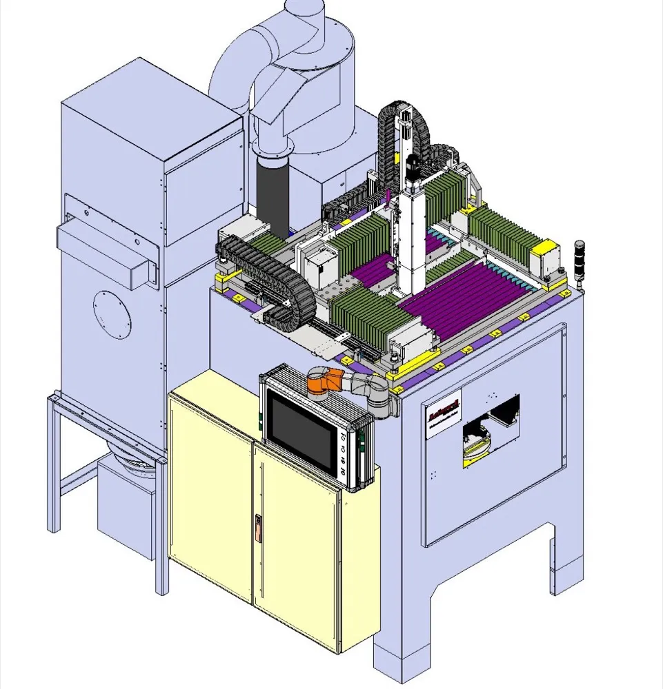
Motionwell has delivered 5-axis CNC shot peening machines for turbine blade surface treatment, a process that puts a controlled compressive stress layer into the blade surface to delay fatigue cracking, written up in the shot peening machine case study. We also participated in the Aerospace Open Innovation Challenge (AOIC) 2024 with A*STAR SIMTech, developing force-controlled robotic grinding for CFRP composite panels, holding 100 N constant contact force through the tool path, and a nacelle paint-removal robot. We serve aerospace OEMs and engine MRO services providers across the region. Loading and unloading machines like these, and the machine tools around them, is covered on our machine tending automation page.
Aerospace work is almost never catalogue work. Each of these machines was a special purpose machine built around one part family, one fixture concept, and one process window; the surface treatment side is covered in detail on our aerospace surface treatment automation page. The constant across all of them is evidence: every parameter traceable, every process step repeatable, every result documented well enough to survive a customer audit. If you are still deciding who should build it, the questions worth asking are in our guide to choosing a system integrator.
For surface-treatment projects, start with the required process outcome. Our shot peening vs shot blasting guide distinguishes controlled peening from surface cleaning and shows how that choice affects the equipment brief.
Selecting Other Finishing and Inspection Processes
A new component may call for robotic polishing to control its surface finish or a deburring process to remove unwanted edge material. Define those outcomes separately from peening intensity and coverage. For conductive parts requiring an appropriate surface or near-surface inspection, eddy current testing introduces a probe, reference sample and scan-coverage requirement.
Automated NDT needs the prescribed product method and retained scan position. ultrasonic inspection workflow covers instrument reference checks and handling interfaces.
Precision finishing needs flatness and roughness defined separately. lapping process evaluation covers plate condition, carriers, cleaning and independent measurement.
Which Aerospace Processes Has Motionwell Automated?
The work combines controlled surface treatment with repeatable part handling. Five-axis peening addresses curved blade surfaces; force-controlled tools follow composite panels; and low-profile tracks extend robot access where installed height is constrained. For a new part family, the first inputs are the treated surfaces, fixture datums, process specification and required production rate. The capability range shows the machine, inspection and handling functions available around those processes.
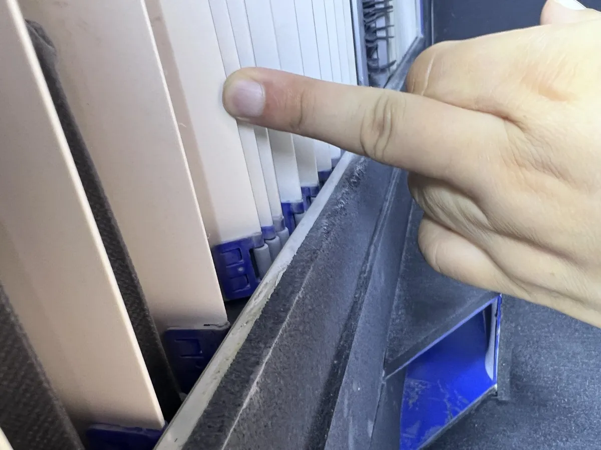
- 5-axis CNC shot peening (X/Y/Z/B/C axes) for turbine blades with G-code control, air curtain containment, and integrated dust extraction
- Force-controlled robotic grinding for CFRP composite panels with 3D scanner guidance and real-time contact force regulation (AOIC 2024 with SIMTech)
- Nacelle surface paint removal using active force-control tools with spindle speed regulation and colour-vision camera feedback
- Precision linear tracks as robot 7th axis: rack and pinion drive, ±0.5 mm repeatability, 1.5 m or more of stroke on a 3 m track, 100mm profile height
- Tight tolerance control with repeatability evidence for aerospace-grade quality acceptance
- Shot peening process validation using Almen strip intensity measurement, coverage verification, and surface finish documentation
- Cobot-assisted blade loading with shaped racks, risk-assessed guarding and safety-related controls designed and validated to ISO 13849
- Full documentation packages with maintenance procedures, calibration schedules, and operator training materials
- Multi-axis CNC motion control with servo drives and G-code programming, so a tool path is edited and re-proved as a programed sequence
- Force-controlled robotic grinding and polishing (A*STAR SIMTech research collaboration)
- High-precision mechanical design: low-profile linear tracks (100mm height, ±0.5 mm repeatability), gantry systems, and custom fixturing
- Instrument integration, automated test sequences, and structured reporting for quality assurance and test lab workflows
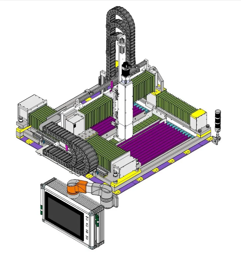
Featured: 5-Axis CNC Shot Peening Machine for Turbine Blades
Motionwell designed and built a 5-axis CNC shot peening machine for aerospace turbine blade surface treatment. The machine uses G-code controlled nozzle positioning across X, Y, Z, B, and C axes to apply uniform compressive stress layers on complex blade geometries, which is what delays fatigue cracking in service.
- Client: Aerospace turbine blade MRO services provider
- Axes: 5-axis CNC (X/Y/Z/B/C) with G-code programming
- Verification: Almen intensity testing and separate coverage checks against the part procedure
- Features: Air curtain containment, dust extraction, Almen strip validation, cobot-assisted loading
- Control: CNC motion control with per-run process parameter logging, so the peening record outlives the shift that produced it
How Is the 5-Axis CNC Shot Peening Machine Configured?
The machine configuration supports a recipe for each blade family. Intensity testing, coverage checks and the approved media specification establish the process settings.
- Control axes: 5-axis (X/Y/Z/B/C), B-axis swing +/-90 degrees, C-axis 360-degree continuous rotation
- Control system: coordinated multi-axis motion control with an operator HMI, the five axes interpolated together instead of moved one after another, because a nozzle that stops to re-orient dwells and leaves a heavier patch on the blade
- Shot media: steel shot, ceramic shot, or glass bead, diameter 0.2-1.0mm
- Peening pressure: 0.3-0.6 MPa
- Coverage: verified using the specified surface-inspection and exposure method, separately from Almen intensity
- Cycle time: an output of the coverage specification, settled per blade family at commissioning
- Blade racks: comb profile shaped to blade geometry, dual-side access
- Cobot-assisted loading for unattended operation
- Machine footprint: approximately 2.5m x 2.0m x 2.5m
- Integrated dust extraction system with filter cartridge
- G-code programming with M-code functions: M03/M05 for peening start/stop, M08/M09 for air curtain, M212/M213 for dust extraction
Why Does CFRP Grinding Need Force Control?
Position control alone does not work on composite. A robot commanded to a fixed path will press harder wherever the panel sits proud of its nominal geometry, and composite answers that with delamination, a scrap part. Force control inverts the problem: the robot holds contact force constant (100 N on the AOIC build) and lets the path float to whatever the real surface demands.
The CFRP composite grinding system developed with A*STAR SIMTech uses:
- 3D scanner guidance for surface mapping before grinding
- Real-time contact force regulation during grinding to prevent composite delamination
- Active force-control spindle with speed regulation
- Colour-vision camera feedback for paint removal depth monitoring, using the same machine vision inspection toolset we deploy elsewhere
- Application: nacelle surface reconditioning and CFRP panel finishing
When Does a Robot Need a 7th-Axis Linear Track?
The short version: when the parts are longer than the robot’s reach, or when one robot has to serve several stations that will not fit inside a single working envelope. Buying a bigger robot to cover a long part usually costs more than putting a normal robot on a track, and it does nothing for the multi-station case. Motionwell designs ultra-low-profile linear tracks as robot seventh axes:
- Track total height: 100mm profile, low enough to avoid a floor pit that most tracks in this payload class require
- Slide platform load capacity: 1.5 tonnes
- Track length: configurable; delivered configuration 3 m track, 1.5 m or more of stroke
- Maximum travel speed: 500mm/s
- Repeat positioning accuracy: +/-0.5 mm (rack and pinion drive with encoder feedback)
- Drive: servo motor + planetary gearbox + ground-grade rack and pinion
- Guide: dual linear ball bearing rails
- No pit installation required, bolts directly to factory floor
- Integrates with the robot controller as a coordinated external axis, so track motion is planned with the arm, which is the difference between the arm reaching while the carriage is still moving and the arm waiting for the carriage to stop
The same track design carries palletizing and machine-tending robots outside aerospace; the warehouse and intralogistics page covers the heavy-payload variants.