
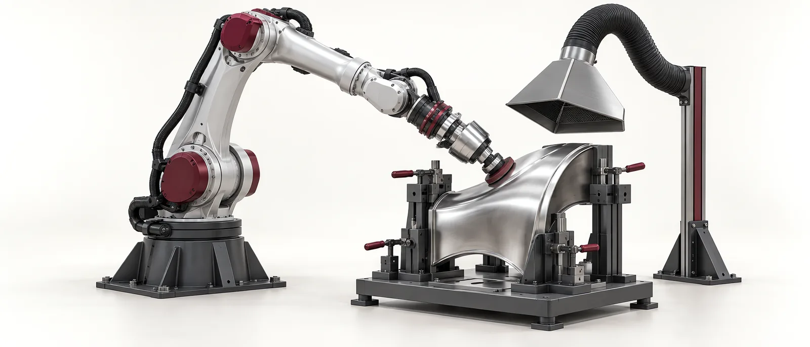
Conceptual equipment illustration.
Robotic polishing needs a defined surface result and a controlled way of producing it. Repeating a path is only part of the process: contact force, abrasive condition, tool speed, overlap and the incoming surface all influence the finish.
Begin with the defect or texture that must change. Removing machining marks, improving gloss and blending a local repair are different tasks. Each needs an acceptance method that can distinguish an improved appearance from an acceptable part.
Turn the Surface Requirement Into a Trial
Identify the areas to polish and the features to preserve. Include edges, holes, thin walls and surfaces that must not be contacted. For aerospace and precision components, connect the finishing operation to the applicable drawing and process requirements.
Select trial parts that represent the incoming variation, not only the easiest surface. Photograph and measure the relevant areas before processing, then repeat the same observations afterwards. Keep the lighting and measurement method consistent when comparing finishes.
What Force Control Adds
A position-controlled path defines where the robot moves. Contact-force control or a compliant tool arrangement addresses how the finishing tool presses against the surface as geometry and contact conditions vary. These are related but distinct responsibilities.
FerRobotics’ force-compliant tooling is an example of equipment designed to manage contact force in robotic surface finishing. Tool selection still needs to account for the process direction, available travel and expected contact changes.
Maintaining a force setting does not guarantee uniform removal. A tool may have a different contact patch at an edge, on a curved face or as its abrasive wears. Trial those regions separately before applying one recipe to the entire part.
Build the Recipe in Controlled Steps
- Establish a repeatable locating and clamping arrangement. Check that the part does not move under the finishing load.
- Choose the abrasive or polishing medium for the incoming surface and required result.
- Establish a starting contact condition and path on a representative area.
- Change one process variable at a time and retain the before-and-after evidence.
- Extend the path to transitions and edges, then test the complete component.
- Repeat with a worn tool to establish replacement or compensation criteria.
The mechanical design review should include tool access and fixture stiffness. It should also show how consumables are changed without disturbing the part datum or tool alignment.
Watch the Edges and the Tool Life
A polished face can look consistent while its edges lose too much material. Inspect edge shape and protected features as well as the broad surface. Where the tool approaches or leaves the workpiece, examine dwell and contact transitions closely.
Record tool identity and accumulated use with trial results. If finish changes gradually, compare tool condition before changing the robot programme. A new abrasive and a worn one may need different treatment, but that difference should be established through the process trial.
Keep polishing distinct from other automated surface-treatment processes. A shot-peening requirement, for example, is not satisfied by achieving a visually smooth surface.
Define What the Cell Must Record
A practical production record connects the part or batch to the recipe, tool condition, process status and required inspection. Include interruptions: stopping in contact with the surface may affect a local area even when the programme later finishes.
Acceptance should cover the complete cycle, including loading, process services, extraction or collection appropriate to the material, tool changes and fault recovery. Measure accepted output with these activities included.
For integrating the robot, tooling and controls, see Motionwell’s robot integration services. Talk to us about the surface result you need.