
Motionwell Automation provides mechanical design services in Singapore as the front end of machines we then build, with an in-house design team of eight working in SolidWorks from a design centre at 20 Woodlands Link, in the same industrial estate as the assembly floor and the machining shop that cuts the parts. Machine design simulation means two different activities at two different points here. The first is offline robot simulation, which verifies reach, clearance and cycle time before anything is fabricated. That is how up to 50 layer patterns on our delivered carton palletizing cell were programmed, with pallet stability and cycle time checked offline, because offline is the only place where a reach or a stability answer is still free to be wrong. The second is the force and moving-mass analysis that sizes a frame and its drives before steel is ordered.
The company has delivered more than 150 special purpose machines since 2014 under ISO 9001:2015 and bizSAFE Level 3. The headline is this: almost everything that decides whether a machine holds tolerance, gets serviced and changes over is settled on a screen in the opening weeks, while it is still free to change, and the parts that get analysed hardest are frequently not the parts that decide the outcome.
Design here is drawn by people who have to make it work at factory acceptance testing in the same building, so it leans towards what our own shop can machine, weld and inspect. That is an advantage on manufacturability and a constraint where a machine needs an exotic process.
The structural arithmetic for long spans is on our gantry and truss robot page, the heavy end of the moving-mass problem is on the heavy duty robot track page, and the full project sequence around this work is in our guide to special purpose machine design.
What Gets Decided at Design Stage and Cannot Be Changed Later?
Four things, and none of them is a component choice: frame stiffness, access, the envelope the machine occupies, and the changeover concept.
| Decision | What it actually sets | Where it is still free | What changing it costs after fabrication |
|---|---|---|---|
| Frame stiffness | Placement accuracy at the far end of the envelope, and how long the machine takes to stop moving | Concept, while section depth, span and column spacing are all variables | A new frame, because you cannot add section to a welded structure that is already square |
| Access | Whether a person can reach the wear items, the fault positions and the format parts | The concept layout, before the guard line and the cabinet position are fixed | Cutting into a finished machine, or living with the access you have for its whole life |
| Envelope | Floor area, clear height, aisle, door swing, and what has to be free above and beside the machine | Before the layout is signed off | Moving the machine, moving the services around it, or discovering on site that it does not fit |
| Changeover concept | Whether each axis of variation lives in a recipe or in a change part | Before the layout is frozen | A second feeding technology or a new change part set, which is a rebuild |
Two of those are worth a sentence more. Changeover is easily assumed to be a decision that can wait, and it is not: a recipe change is a setting the machine moves under software control, while a change part is geometry that has to be made, stored, identified and fitted, and which of the two you get is decided by whether the axis was motorised on the drawing. The reasoning and the delivered numbers are on our filling line changeover page.
The envelope decision includes kinematics, which is the least reversible choice on the page. Our 5-axis CNC shot peening machine for turbine blades runs X, Y, Z, B and C simultaneously because holding 100 to 200 per cent coverage on a curved blade means presenting the nozzle to the surface at a controlled angle, and reaching it is not enough. Three axes would have reached every point on that blade and produced an uneven result along the chord. Axis count is a process decision made before any structure exists, and a machine cannot be given another degree of freedom later without becoming a different machine.
Why Does Deflection Size a Machine Frame Before Strength Does?
A frame that is strong enough can still be far too flexible to hold tolerance, and only one of those two properties gets checked by intuition. Strength answers whether the structure breaks. Stiffness answers how far it moves before it stops. A positioning machine rarely goes anywhere near its yield stress, and it fails its acceptance test at a fraction of a millimetre.
The trap is the response that follows. Faced with a droop figure, the reflex is a stronger material, and it does almost nothing, because elastic modulus barely varies across carbon and alloy steels while strength varies a great deal. What buys stiffness is geometry: section depth, the span between supports, and how directly the load path gets back to the floor. Span in particular punishes optimism, and the arithmetic behind that is set out on the gantry and truss robot page.
Deflection has a second cost that is easier to miss because it appears in the cycle time. A structure that bends also rings, so a compliant frame does not simply place the tool in the wrong spot, it takes longer to stop moving before the gripper can open. That penalty is paid on every cycle for the life of the machine. It gets worse with unsupported length, which is why a Z stroke specified generously in case it is useful later is not free, and why overhang between the tool and the guide rails matters as much as the stroke does. The vertical-axis version of that argument is on our servo lift and precision positioning page.
One figure is worth writing into a specification: placement measured at the worst position in the envelope with the tool loaded. On a beam that position is near mid-span. It is a number a buyer can verify with an indicator at factory acceptance testing, which no amount of structural description is.
Load-path decisions become concrete in a tensile testing machine or functional test fixture: support movement can alter the measurement or contact condition. A vibration testing fixture also needs its dynamic response assessed across the test range.
Process forces introduce different constraints. A robotic welding fixture must preserve joint access, while robotic polishing needs controlled contact without excessive edge removal. A deburring machine needs access to the burr and support for the features that must remain unchanged.
Why Does Moving Mass Have to Be Analysed Before Steel Is Committed?
Moving mass and inertia size the drive, and the drive sizes almost everything downstream of it. Holding a load and moving one are different calculations: a static hold needs force, while a move needs torque to accelerate inertia, and it is inertia that the motor fights. Motor sizing is a torque calculation from inertia, friction, acceleration and duty. Get the mass wrong at concept and every number after it is wrong too.
The order of consequences is what makes this urgent. Mass sets the force, the force sets the drive and gearing, those set the guide size, the guide and the reaction loads set the frame section, and the frame section sets the footprint and the guard line. Nothing in that sequence can be resized on its own. The heavy-mass version of that chain, where the carriage is mostly moving itself, is worked through on our heavy duty robot track page.
There is a failure mode specific to skipping this. An axis sized only against its move time meets that time on paper and then cannot stop cleanly, and the usual response is a larger motor, which reaches the same ceiling sooner, because on a rack-driven long axis that limit is tooth root bending and flank contact stress at the pinion. Nothing in software fixes an axis that was sized against the wrong mass.
Two inputs are easy to leave out of the mass figure. The tooling is one: rated payload is measured at the tool flange, so whatever the gripper weighs comes out of the budget left for the part, and a load held away from the flange limits the arm by moment. The other is the heaviest variant nobody mentioned, because part weights drift and someone adds a heavier version next year. The tooling side of that arithmetic is on our end of arm tooling page.
The required motion also decides the actuator architecture. Compare pneumatic and electric linear actuation against the load, guidance and feedback requirements before fixing the mounting envelope.
Which Design Decisions Benefit From Finite Element Analysis?
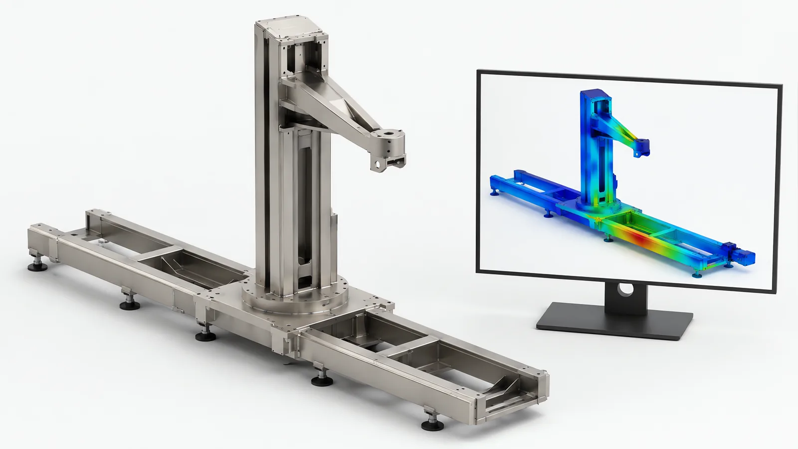
Use FEA where load distribution, deformation, vibration or local stress is difficult to resolve with simpler calculations. Long spans and lifting structures deserve particular attention. Define the question before building the model: allowable tool-point deflection, stress at a joint, natural frequency or another result that changes the design. Check the model’s loads and supports against the real machine, then verify the relevant behaviour during build and testing.
| Structure | Analyse it | Reason |
|---|---|---|
| Long span carrying the tool at its worst position | Yes | The deflection number there is the acceptance figure, and no intuition is reliable about it |
| Tall or cantilevered Z column | Yes | Stiffness falls quickly with unsupported length, and the settling time follows it |
| Lifting structure, or anything passing a load over a walkway | Yes | Consequence, not tolerance; in Singapore lifting equipment is also certified by an approved authorised examiner before use |
| Welded base under a machine that has to stay flat | Sometimes | Worth it where distortion after welding is the real risk, which is a fabrication question as much as a stress one |
| Guard bracket, cable tray, cover panel, cabinet gland plate | No | A standard section and a hand calculation settle it, and the load case is trivial |
| A plate bolted flat to a machined base | No | It is not carrying bending; the joint and the flatness decide the result |
How to read a result matters more than whether one exists. A stress plot proves nothing on its own, so ask three questions of any analysis in a quotation. Which position and load case was modelled, since a machine is not worst at the same place it is convenient to model. What was assumed rigid, because an assumption that the base is infinitely stiff moves the answer more than the mesh does. And what single measurable number came out of it, since an analysis whose prediction cannot be checked with an indicator on the finished machine has not been validated by anyone, including the person who ran it.
The boundary is worth stating plainly. Analysis is the wrong instrument for a good deal of what actually goes wrong on a machine, because friction, part-to-part variation, feeder behaviour, chip and coolant contamination and thermal drift across a shift are not in the model. Those get proved on your real parts, at commissioning and at factory acceptance testing, which is a different kind of evidence and usually the more valuable one.
What Does Offline Simulation Prove Before the Cell Exists?
It proves reach, clearance and cycle structure, and it earns its place because a pose that cannot be reached is a mechanical problem. Discovering it in a model costs a redraw; discovering it after the pedestal is grouted costs a layout.
Three things belong inside the simulation that frequently sit outside it. The dress pack is the first: a wrist axis rotating through a large angle winds its cabling, and the travel limit that follows gets discovered during programming unless somebody models it. The extremes of travel are the second, because on a track the pose that fails is usually at one end of the stroke where nobody checked. The third is the worst layer or the worst position.
What it does not prove is worth being equally clear about. A simulation inherits whatever assumptions you fed it, so a cycle time from a model carries the same optimism as a datasheet figure measured gate to gate with a dummy load: the vision acquisition, the settling before a vacuum releases, the gripper actuation and the PLC handshake are what usually decide whether a station makes rate, and those are timed on real parts. On a robot riding a linear axis, the simulation typically covers the arm properly while the transit between stations remains a spreadsheet estimate. And no kinematic model has an opinion on whether your part sits in the nest the same way every cycle, which is a common way a cell fails in production. How that gets designed against is on our robot integration services page.
On a surface-treatment cell, the fixture and nozzle path must expose the specified surfaces. The distinction between shot peening and shot blasting matters here: surface cleaning and a controlled peening process call for different acceptance evidence, even when the handling equipment looks similar.
What Changes When a Machine Is Drawn for the Shop That Will Build It?
Design for manufacture stops being a slogan when the designer has stood at the machine. Our mechanical designers have direct experience operating CNC machines, which removes the designs that look correct on screen and are impractical to cut. The rules that follow are unglamorous: machined components use standard tooling, sheet metal follows standard bend radii, and weldments are laid out so they can be inspected.
The expensive habit is a tolerance the function does not need. Each step tighter moves a part into a slower and dearer process, and the step is a cliff.
| Process | Typical components | Tolerance capability | The design rule that follows |
|---|---|---|---|
| CNC milling | Base plates, mounting brackets, fixture bodies | ±0.01 mm | Datum from one face where you can; a part re-fixtured to hold a tolerance is two setups |
| CNC turning | Shafts, bushings, spacers | ±0.01 mm | Keep precision features on one diameter family |
| Wire EDM | Precision die components, tight-tolerance slots | ±0.005 mm | Reserve it for the feature that genuinely needs it |
| Sheet metal | Enclosure panels, guards, cable trays | ±0.1 mm | Do not locate a precision feature off a folded panel; it is a cover |
Two consequences follow that a buyer can check in a drawing pack. Precision features should be concentrated on a small number of machined parts and the rest of the structure allowed to be ordinary, because that is what lets a sheet metal guard cost what a guard should cost. And every dimension that carries a tolerance should be inspectable with equipment somebody actually owns, which is why weldment access for inspection is a design decision. Where components are machined to our drawings by qualified machining partners, that inspectability is the difference between a part being accepted and a part being argued about.
Why Does Design for Maintenance Get Traded Away Quietly?
It is the one requirement with no acceptance test behind it. Cycle time, accuracy and repeatability are all measured at factory acceptance testing in front of the buyer. How long it takes to change a bearing is not on that list, so under schedule pressure the service clearance is the space that gets used for something else.
It is preventable at concept, and cheaply, because 3D concept modelling in SolidWorks validates spatial constraints, operator access and maintenance clearances before procurement begins. What that review needs is four questions asked out loud against the model.
- Where does a person stand to service each item, and is that place inside the guard? If it is, every service visit is a lockout, and that changes how often the service actually happens.
- What has to come off first? A wear item behind a cable tray behind a guard panel is a two-hour job that looks like a ten-minute one.
- Can the machine be driven to a service position, and is that position in the program? On single-beam gantry builds this is settled at design stage by deciding whether the Z head can be driven to one end of the row; double-beam builds carry a maintenance walkway and railings for the same reason.
- After a fault, how does the part get out? Somebody has to extract a workpiece from a closed station with a gripper still holding it, and if that recovery was never designed the operator invents one, usually by defeating something.
The trades here are real and should be made with open eyes. Mounting a collaborative arm overhead frees the floor for conveyors and operator access and costs easy maintenance access; that is a trade. A part that jams, such as a cap track, needs to be cleared and changed without tools, because it will jam and an operator will be standing there when it does. And the maintenance schedule itself is a design output: levelling and foundation checks belong in it on any long axis, alongside the mechanical drawings, electrical schematics, PLC program documentation, operator manuals and spare parts lists that ship with the machine.
Why Must Tolerance Stack-Up Be Run Against the Part, Not the Machine?
The machine’s repeatability is one term in a sum, and rarely the largest one. Our linear gantry series quotes a figure per class that loosens as the structure gets longer and heavier, since deflection, thermal growth and drive stiffness all worsen with size; our low-profile seventh-axis track repeat-positions to ±0.5 mm; the delivered SCARA panel assembly cell works at ±0.01 mm repeat positioning. Each of those is a machine returning to a taught point. None of them is a statement about where your part ends up.
| Contributor | What it is | Who owns it | What closes it |
|---|---|---|---|
| Machine repeatability | Return to a taught position, on the datasheet | The builder | Already the smallest term on most cells |
| Presentation and fixturing | Where the part sits when the machine arrives for it | The builder, from your part drawing | Locating on stable features, and a seating confirmation that measures |
| Pick-up variation | How the part sits in the gripper after it is picked | The builder | A tool proven on samples across the whole spread, plus compliance where the pick cannot be made exact |
| Part-to-part tolerance | Your component supplier’s real spread, which is rarely the drawing value | You and your supplier | Measured incoming data agreed before the nest geometry is fixed |
| Station-to-station transfer | Docking, parking and handover between two systems | The builder, across an interface | A docking feature, hand-eye vision measuring the real offset, and compliance for what is left |
| Drift after handover | Floor markings wear, a leg gets nudged, a foot settles | You, in the maintenance schedule | Re-referencing after foundation work, and a checkable datum feature designed in |
The transfer interface can dominate the tolerance budget. A mobile base may park within roughly plus or minus 50 mm while a rack handoff requires sub-millimetre placement. Select physical docking, hand-eye correction or compliant tooling to close the gap, then test the complete handoff across the expected docking spread and station movement. Our laboratory automation systems use vision correction before the arm commits to the rack or instrument fixture.
So the stack has to be run from the feature on your part that must be located, backwards through the gripper, the nest, the axis and the frame, at the position and temperature where the machine is worst. That needs the drawing of your worst part, which is why a design review that only ever sees a nominal model has not tested the design at all.
What Do the Design Review Gates Actually Check?
Each gate is a decision point, and what matters about each is what stops being free once it closes.
| Gate | What is produced | What is still open afterwards | What the gate freezes |
|---|---|---|---|
| Concept review, 2 to 4 weeks | Process flow with cycle time per station, preliminary 3D layout showing footprint and operator access, component selection, risk register, rough order of magnitude budget | Component brands, HMI layout, recipe structure | Kinematics, frame concept, envelope, changeover concept, safeguarding strategy |
| Detail engineering, 4 to 6 weeks | Full mechanical design in SolidWorks, electrical schematics, pneumatic layouts, control architecture, safety circuit design, bill of materials | Program structure, screen design, spares list | Anything that changes a machined part or a fabricated section |
| Fabrication release, 6 to 8 weeks of build | Parts machined to our drawings, assembly following a documented build procedure with quality checkpoints | Software, sequence tuning, documentation | Every mechanical decision above; changes here are rework |
| Factory acceptance testing, 2 to 4 weeks | Cycle time, accuracy and repeatability demonstrated to you at Woodlands Link with your parts | Recipes, thresholds, operator procedures | Anything requiring a part to be re-made |
The largest schedule risk in this sequence is not in the machine at all: it is late finalisation of your product design. If the part geometry moves after detail engineering has begun, the tooling changes and the fixture usually changes with it. The same logic applies to your own requirements document, and how to write one that survives this process is on our automation URS page.
Two compliance points belong at the first gate. The risk assessment is a design input, because the safeguarding it demands changes the layout, the access points and the guard line, and each safety function then carries a required performance level under ISO 13849-1:2023 that has to be architected early; the physical scope that follows is on our machine safety and CE marking page. And for a machine destined for the EU, Regulation (EU) 2023/1230 applies from 20 January 2027 with no transitional period, and it is the first EU machinery law to put software integrity, updates and connected functions alongside mechanical safety, which changes what the design pack has to contain for a networked machine. A machine being designed now can be documented against it voluntarily, and that is a decision for the concept gate because it is a documentation architecture.
When Is a Separate Design Package the Wrong Thing to Buy?
Five cases, and each one is cheaper to name now than to discover in week three.
A proven standard machine covers the process. Where a catalogue machine handles your product at your rate for less than anything we would design, that is the recommendation you get, and it costs a conversation to establish.
The product is not frozen. Detail engineering against a moving geometry buys drawings that get redrawn at your expense. If the part is still changing, the first purchase worth making is a shorter concept study that brackets the options.
What you actually need is a requirements document. If the rate, the variants, the utilities and the acceptance criteria have not been written down anywhere, that gap is cheaper to close first, and closing it makes every subsequent quotation comparable to every other one.
The problem is upstream of the machine. Where parts arrive in a heap, where the presentation is inconsistent or where the bottleneck is a process dwell, better mechanical design of the wrong station changes nothing measurable.
The analysis is wanted as a document. If a report is needed to satisfy a third party, say so at the outset. That is a different piece of work with a different deliverable, priced and scoped as a report, and an engineering study dressed up as one satisfies nobody who reads it closely.
Design, fabrication, assembly and testing all happen at Woodlands Link with the design team in the same estate as the shop, which is why a Singapore buyer attends the factory acceptance test without flying to it. That matters more on design work than it appears to, because the questions that decide a machine get answered by putting a real part into a real fixture in front of the engineer who drew it. The questions worth asking any builder about their design capability, including us, are set out in our guide to selecting a system integrator.
Standards Used in Machine Design and Validation
These references inform the design, testing and documentation described on this page. Each row links to its primary source and records the edition checked.
| Standard | Current edition | What it means for your machine |
|---|---|---|
| ISO 13849-1: Safety of machinery, safety-related parts of control systems | ISO 13849-1:2023 | Provides the design method for safety-related control functions, including architecture, component reliability, diagnostic coverage and common-cause failure measures. The machine risk assessment establishes the required Performance Level; design calculations and validation provide the evidence for each function.Checked 1 Sep 2026 against ISO 10218-1:2025 normative references |
| Regulation (EU) 2023/1230: the EU Machinery Regulation | (EU) 2023/1230 (changeover pending) | Applies on a mandatory basis from 20 January 2027, replacing Machinery Directive 2006/42/EC. Project planning should align the intended EU market date with the conformity assessment and technical documentation, including relevant software integrity and connected-function requirements. The European Commission permits voluntary declarations against the Regulation before that date, while the Directive remains applicable.Checked 1 Sep 2026 against European Commission, Machinery page (single-market-economy.ec.europa.eu/sectors/mechanical-engineering/machinery_en); EU-OSHA legislation register |
Frequently Asked Questions
Is a stiffer machine frame just a heavier one?
No. Mass and stiffness are different properties, and adding plate to a section that is the wrong shape buys very little of the second while costing a great deal of the first. Extra moving mass has to be accelerated and stopped on every cycle, so it comes back as drive torque, as heat in the motor and as settling time you wait for before the gripper can open. What buys stiffness is section depth, a shorter unsupported span and another column, none of which weigh much.
Do you run finite element analysis on every machine you design?
We select the analysis depth from the load path, accuracy requirement and risk. Long spans, tall columns, lifting structures and parts with complex loading often benefit from FEA. Simpler components may be sized with established calculations and verified by inspection or testing. The review records the loads, boundary conditions and acceptance limits so the result supports a design decision.
How long is the design phase before fabrication can start?
Concept design typically takes 2 to 4 weeks before concept approval. Detail engineering then takes about 4 to 6 weeks within a standard 16 to 24 week concept-approval-to-FAT programme; complex or regulated builds can need 24 to 32 weeks to FAT. Procurement and testing are mapped into that schedule, with installation and site qualification shown separately. A firm variant list, sustained rate and agreed acceptance criteria help the design reviews progress.