
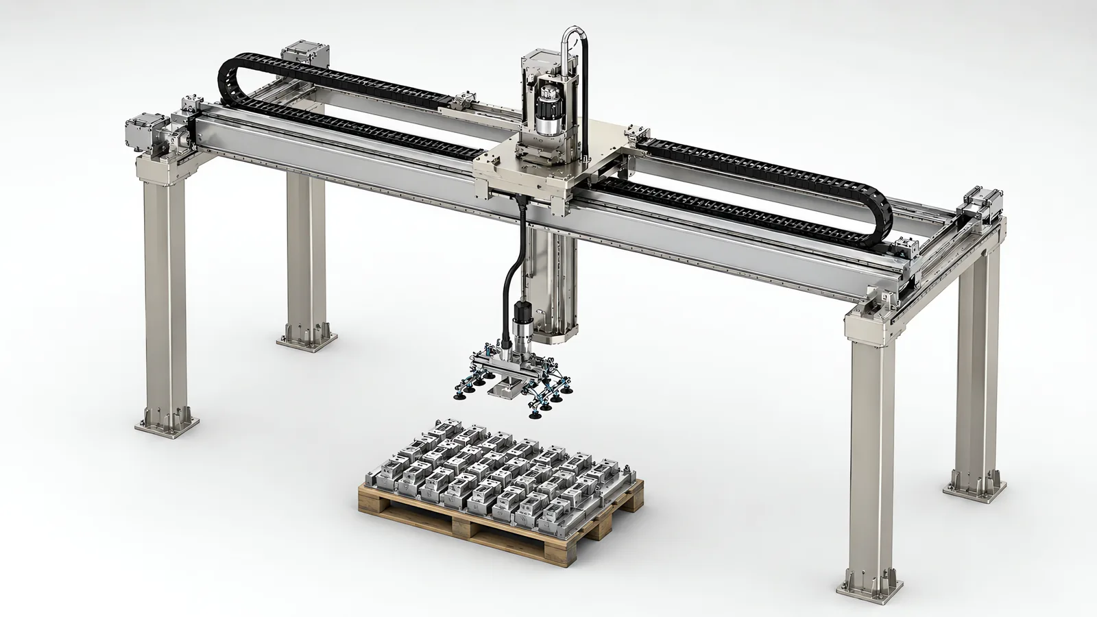
Motionwell Automation designs and builds linear gantry and truss robot systems in Singapore, and this page is about the machine itself: what the structure is, how the series steps, and what has to be settled before anyone can size a beam. Our own linear gantry series runs a compact three-axis aluminium extrusion frame with pneumatic multi-finger grippers, a welded steel single beam for heavier parts along a row of machines, and a double beam bridge on multiple columns where the span or the load outgrows one section.
The X axis runs on rack and pinion, the beam is built in sections, and the single-beam and double-beam builds can carry one or two independent Z columns. On a row of machine tools, one gantry services more than ten machines. Machines are designed, assembled and tested at our Woodlands Link facility, and the company has delivered more than 150 special purpose machines since 2014 under ISO 9001:2015 and bizSAFE Level 3.
What we design and build is the gantry itself: the frame, the beam, the carriages, the Z columns, the tooling interface, the cable management, the guarding and the controls, all drawn around catalogue servo drives, linear guides and rack. The application of tending machines with a gantry, including the arithmetic for how many machines one beam can hold, is on our machine tending automation page.
What Does Cartesian Kinematics Buy You Structurally?
It buys a different load path, and every other difference in the table below follows from that one. In a gantry the payload is carried by a beam supported at its ends and grounded through columns into the floor or the building steel. In an articulated arm every newton of payload is a moment carried through each joint in turn, back into the base casting.
| Structural property | Cartesian gantry or truss | Articulated six-axis arm |
|---|---|---|
| Load path | Payload into the beam, beam into the columns, columns into the floor or building steel | Payload as a moment at every joint, back through the arm to the base |
| Payload against distance | Falls with span between supports | Falls off with reach, and falls off hardest where you want it |
| How it scales | More beam sections and more rack along X, on the same drives and controller | Change the arm class, and start the reach and payload trade again |
| Envelope shape | A rectangular prism you can draw straight onto a layout | A sphere with a hole in the middle and a base pedestal in the way |
| Degrees of freedom | Three, so the part is presented in the orientation the gantry holds it | Six, so orientation is free within the envelope |
| Where stiffness comes from | Section depth, span and column spacing, all of which are design variables | Fixed by the model you bought |
| Floor area | Travels overhead, so the floor stays clear underneath | Its own cell area, plus access |
| What limits accuracy | Deflection and settling of a long structure, and thermal growth over its length | Joint compliance, gear backlash and reach |
Three consequences of that table are why a gantry gets chosen at all.
Distance is cheap on a beam. Adding travel adds beam, rail and rack, so the payload at the far end of a long run is the payload at the near end. On an arm, reach and payload trade against each other continuously, which is why extending an arm usually means moving up a class or putting it on a track.
The floor stays clear, because the working envelope is overhead and rectangular. A gantry’s envelope draws straight onto a layout as a box over the machines it serves, so the aisle underneath stays walkable and the stations below it keep their own access. An arm claims a fenced circle of floor at ground level, plus the room to get to it.
Orientation is what you give up. Three linear axes deliver the part in the orientation the gripper picked it up in. Where a part must enter a fixture at an angle, no amount of travel substitutes for a wrist. A rotary axis can be added at the Z column, but at that point you are buying articulation on a Cartesian frame and the comparison deserves to be reopened.
Which of the Three Series Fits Your Payload and Span?
Payload, span and beam construction step together. An aluminium extrusion frame does not carry a heavy workpiece, and you do not need a welded double beam to move a light tray between assembly stations. The boundaries below are structural.
| Series | Frame and beam | Where it fits |
|---|---|---|
| Compact three-axis | Aluminium extrusion frame, lightweight and bolted, reconfigurable | Light parts over short runs, and transfer between assembly stations |
| Heavy duty single beam | Welded steel structure, high rigidity, beam built in sections along X | A row of machine tools worked from one beam, carrying one or two Z columns |
| Double beam | Twin-beam bridge on multiple columns, maintenance walkway and safety railing | Wide spans and heavy workpieces, where one section can no longer take the bending and the twist together |
Payload, travel and repeatability are outputs of a build, and they follow from the section depth, the column spacing, the stroke and the moving mass once the part and the layout are known. That is why the boundaries above are written as construction. Traverse speed moves the other way as the machine gets bigger: the compact frame is the quickest of the three and the double beam the slowest, because there is more mass to accelerate and more structure to settle afterwards. On any long axis the binding limit is usually what it costs to stop the moving mass without exciting the structure.
Two cautions before a row of that table gets read as a specification.
Repeatability is not placement accuracy. A repeatability figure describes how tightly the machine returns to a taught point, and nothing more. Whether the part seats is decided elsewhere: by how well it was located before the pick, by gripper repeatability, by debris on a locating face and by fixture wear. Where a part cannot be located mechanically, a camera measures its position before each pick and the controller corrects the move, as set out on our machine vision inspection page.
The gap between the compact and single-beam classes is also real. There is a step in construction between a bolted aluminium frame and a welded steel one, and an application landing between the two gets engineered, never picked off a series table. Say so early, because it changes the frame.
The compact class also appears where nothing heavy is handled at all. On the semi-automatic electronic test machines we build, an XYZ three-axis gantry frame carries the test head down onto the product over a linear guided worktable, which is how a small Cartesian frame delivers a controlled vertical press with a repeatable approach.
When Is a Second Beam Structurally Necessary?
A second beam becomes necessary when the span, the payload or the number of Z carriages puts more into one section than one section should carry. That is a stiffness and torsion question, not a payload rating.
| Consideration | Single beam | Double beam |
|---|---|---|
| Payload | Carried on one section, so the section depth grows with the load | Shared between two beams, so the load stops setting section depth on its own |
| Span | Column spacing set by the section you can justify | Long runs carried on multiple columns along the row |
| Torsion | The Z column hangs offset from the beam, so vertical load also twists it | The bridge closes the load into a box between two beams, so the twist becomes a couple the pair resists |
| Z carriages | One, or two if the beam and carriage length allow it | One or two, with room for both carriages and their services |
| Maintenance access | From below, or from a platform brought to the machine | Maintenance walkway with safety railing and access ladder built into the structure |
| Building interface | Fewer column feet to place on your floor | More column positions, each of which must land somewhere you can put a foot |
| What it costs you | Cheaper, lighter, fewer foundations | More steel, more floor positions, more height |
The torsion row decides more than people expect, because it is not on the payload rating. A single beam carries the Z column and its load hanging to one side of the beam’s own centre, so it bends and twists at once, and the twist reaches the tool as a lateral error that grows with Z extension. Deepening the section helps the bending far more than the torsion. Bridging between two beams changes the mechanism: the pair resists that twist as a couple, which is far stiffer per kilogram of steel than winning it on one section.
Three signals that the second beam has stopped being optional: the span has to grow but the ceiling will not allow a deeper section; two Z columns have to work the same run and one beam does not give enough carriage length to keep them apart; or the machine needs a walkway, which has to sit on something. Where a single beam still wins it wins clearly, and a row of machine tools within what one welded section can carry, with column positions along one side, is what it was drawn for.
Why Does Deflection Over Span, Not the Motor, Usually Set the Beam?
Those are two different sizing problems, and only one of them is easy. Motor sizing is a torque calculation: inertia, friction, acceleration, duty. Beam sizing is a stiffness calculation, and stiffness is a set of decisions about section, span and column spacing that you can still influence at concept review and nobody can change after fabrication.
For a beam carrying a load between supports, deflection scales with the cube of the span and inversely with the second moment of area of the section. Doubling the unsupported span is therefore roughly a factor of eight in droop at the same section, and the recovery comes from section depth or another column. A quotation that answers a longer span with a larger motor is answering the wrong question.
Static droop is only the visible half. The moving half usually costs the cycle, because the beam is a spring and the carriage is a mass. Every stop excites an oscillation, and until it decays the Z column cannot descend into a fixture with any confidence, so settle time joins the cycle whether or not it appears on a timing chart. A deeper section raises the natural frequency and shortens the settle. A faster drive shortens the move and lengthens it.
Where you measure matters as much as what you measure. For a simply supported beam the worst deflection is near mid-span, not at the end of travel, and with two Z carriages it is both of them near mid-span at once. Ask for the deflection figure at that position, with the tool loaded. Long travel adds a second effect that only appears at length: a steel structure tens of metres long grows and shrinks with shop floor temperature, so if the machine homes at one end and works at the other, that growth lands in the placement error at the far end. Referencing against a datum near the work is one way out of it.
All of which makes deflection under load the acceptance test worth writing into a specification. Placement measured at the far end of the envelope with the tool loaded is where compliance in the tool, deflection in the structure and inertia in the moving mass appear together, and a figure taken anywhere else describes a machine you are not buying. The same discipline applied to tooling is on our end of arm tooling page.
Achievable repeatability loosens step by step across the series for exactly this reason. The machines are not built to a worse standard as they get bigger; they get longer, heavier and more flexible, and the figure a build can hold follows the structure.
What Do Two Z Heads on One Beam Actually Change?
Mechanically, they turn one carriage into two independent lifting mechanisms on the same beam, each with its own gripper set. On the dual Z-axis builds each column carries a pair of pneumatic grippers, so the head handles four workpieces at once: one column lifts finished parts out while the other lowers blanks in, and load and unload happen in one visit instead of two.
What that buys is visits. Across a row of machines a dual-Z head halves the number of trips the gantry has to make, and it is the trips that limit how many machines one beam can hold. How that gain translates into machines served is worked through in the cycle-time arithmetic on our machine tending automation page.
What the second head costs on the structure side is discussed less often. Both columns and both gripper sets ride the beam on every move, working or not, so that mass sits permanently in the deflection case, the settle time and the drive sizing. Two carriages also need enough beam to sit on without colliding, and enough length at each end for both to reach the same station, which on a shorter single beam is sometimes why the answer comes back as one head.
Two independently driven carriages on one rail is also a machine that can drive into itself, so the collision envelope belongs in the motion controller as a hard limit, checked at commissioning and never left to the program to respect. And there is two of everything else: two Z drives, two sets of tooling, and twice the air and signals to route along the full travel, so the cable carrier and its fill get sized alongside the tooling.
What Drives the X Axis on a Long-Travel Gantry?
Long travel eliminates most of the options before anyone gets to preference. Here is what survives and why.
| Drive on the long axis | Why it works | Where it stops |
|---|---|---|
| Rack and pinion | Rack joins in sections, so travel is not limited by the length any one component can be made in, and it is stiff enough for heavy loads at speed; ground rack gives real positioning accuracy | Needs lubrication and reasonable cleanliness at the teeth, and backlash has to be managed by preload or a second pinion |
| Timing belt | Cheap, quiet, forgiving, no lubrication, entirely adequate on short light axes | Belt stretch grows with length and the natural frequency falls with it, so long belts wind up and settle slowly |
| Ball screw | Excellent stiffness and resolution on short precision axes, and one of the two options our series specifies on Y | Critical speed and whip limit usable length; a screw metres long is the wrong component |
| Linear motor | No contact, no backlash, high dynamics | Cost per metre of track, and a magnet track exposed in a dirty environment |
That is why the X axis in our gantry series runs on rack and pinion, why the Y axis uses a ball screw or a timing belt depending on the class, and why the Z runs on precision linear guides. The same reasoning shapes the related products: the low-profile seventh-axis track drives ground-grade rack and pinion from a servo motor and planetary gearbox, and the dual-rail truss manipulators drive theirs through a common pivot shaft on V-groove roller guides, because a roller on a V edge sheds the debris a ball guide would ingest.
Long positioning axes commonly use servo drives with absolute position feedback. The feedback system retains or recovers the axis reference after power restoration, subject to its encoder and backup arrangement; brakes or mechanical holding devices keep a load in place while power is absent. On a dual-drive bridge, the controller also synchronizes the two sides to prevent racking. An axis needing speed control without precise positioning may use an induction motor and VFD. The drive comparison is in our note on choosing between servo and stepper drives.
Cable management is not a detail on a long axis. A truss manipulator with 12 metres of Y-axis travel has to deliver air and signals to a tool that never stops moving, so the carrier and the cable inside it are specified for continuous flexing over that travel, and the bend radius gets respected. Ordinary cable in a moving carrier work-hardens at the bend and then fails intermittently, which gets diagnosed as a sensor or a drive fault two or three times before anyone opens the carrier.
Should the Frame Be Aluminium Extrusion or Welded Steel?
The payload class mostly decides this, and the environment decides the finish. It is not an open choice at every size.
| Aluminium extrusion frame | Welded steel frame | |
|---|---|---|
| Where it sits in the series | The compact three-axis class | The single beam and the double beam above it |
| Stiffness per section | Lower modulus, so more section is needed for the same deflection | Higher modulus, so a given depth of section goes further |
| Where compliance hides | In the bolted joints, and bolted joints can creep under vibration | In the welds, which is a fabrication quality question |
| Geometry | Limited to what the profile catalogue and the connector set allow | Any geometry that can be cut and welded |
| Distortion | None from fabrication | Welding distorts, so critical faces are machined after welding and stress relief |
| Reconfigurable | Yes, which is genuinely useful on a machine that will be modified | No, it is what it is |
| Finish | Anodised, and clean enough for electronics and cleanroom work | Paint or powder coat, which is a maintenance item and a particle source |
| Moving mass | Lower, which helps acceleration and settling | Higher, which is what you want under a heavy payload |
The environment is the second filter, and our material selection across machine types runs the same way: mild steel or aluminium extrusion for general industrial work, anodised 6061-T6 aluminium with a hard anodise for electronics and cleanroom builds, and stainless for GMP and washdown-duty machines. Anything sliding, rolling, meshing or flexing sheds particles as it wears, so a gantry inside a classified zone gets its mechanism enclosed or moved below the product plane.
One note on aluminium is worth stating plainly. Extrusion is specified on the compact class as a lightweight frame, and it is not a route to the stiffness a welded section gives. Holding a heavy payload over a long span on extrusion means adding so much section that the weight and cost advantage has already gone.
How Do You Guard a Machine Whose Working Envelope Is Overhead?
The guarding comes out of the risk assessment, and a perimeter fence answers only part of what that assessment raises. Start from an ISO 12100 risk assessment and let it drive the design. The robot and the integrated system are covered by ISO 10218-1:2025 and ISO 10218-2, with each safety function carrying a required performance level under ISO 13849-1:2023, calculated and validated. The 2025 edition of ISO 10218-1 references the 2023 edition of ISO 13849-1, so a design documented against the older edition will need its performance level calculations restated when the machine is reassessed.
The ordinary guarding standards still set the physical design. ISO 13857 fixes safety distances for reaching over, under, around and through openings, which sets mesh aperture against standoff. ISO 13855 governs scanner and light curtain positioning, with the minimum distance coming from the approach speed constant, taken as 2,000 mm/s up to 500 mm and 1,600 mm/s beyond, plus measured stopping performance. ISO 14119 covers interlocking devices and how hard each is to defeat.
Four things are specific to a machine working above head height.
The travel path crosses ground a fence does not. A perimeter guard controls who walks in at floor level and does nothing about a load travelling over an aisle, a walkway or a workstation somebody stands at. Settle the route at layout stage, either keeping the loaded path off the areas people occupy or containing what is underneath it. That decision is nearly free before the columns are placed and expensive afterwards.
The grip has to survive losing its utilities, since a fence does not catch what a gripper drops. The design question is whether loss of air or power releases the load, and the answers are a mechanically retained grip, a design that fails closed, or containment under the path.
The maintenance route is part of the machine. Double beam builds carry a maintenance walkway with safety railing and an access ladder, which is an access route at height on your own machine and needs its own assessment, its own lockout point and a defined way of getting somebody down again. That is also why a walkway is a specification item: retrofitting one onto a beam that was not designed for it is not a small job.
Stopping performance gets measured on the built machine. A long axis carrying a loaded Z column at full traverse speed has run-down behaviour that no catalogue predicts, and it has to be measured before any scanner distance calculated to ISO 13855 can be confirmed.
Singapore does not require CE marking, but the Workplace Safety and Health Act requires dangerous parts of machinery to be securely fenced, and machines incorporating lifting equipment must be certified by an approved authorised examiner before use, which is a live question on a gantry. We deliver the physical scope that follows: guard fencing and interlocked access doors, safety laser scanners, safety-rated stop circuits, LVD and CE testing, and MOM lifting certification, as set out on our machine safety and CE marking page.
What Has to Be Specified Before a Gantry Can Be Sized?
Four things decide the structure, and none of them is the drive.
- The heaviest part, plus the tool. Gripper body, fingers, manifold, valves and cabling come out of the payload before the part gets any, and the centre of mass matters as much as the total.
- The envelope in three numbers, measured to the extremes actually reached, including the top of the tallest stack and the depth of the deepest fixture.
- Where columns can land, and what is already overhead. Column positions are a floor constraint, and crane rails, ducting, sprinkler heads and roof trusses change concepts more often than anything else on this list.
- Placement tolerance and where it is measured. A tolerance at the far end of the envelope with the tool loaded is a specification. A single repeatability figure is a datasheet line.
Duty, environment and the interface list decide what it costs to build, and they belong in the same enquiry.
Lead time runs 16 to 24 weeks from concept approval to factory acceptance testing on a standard build, and 24 to 32 weeks where cleanroom compatibility or full validation documentation applies. Design, fabrication, assembly and testing happen at Woodlands Link with an in-house design team of eight, so a Singapore buyer attends the factory acceptance test without flying to it. How a build of this shape is scoped and commissioned is in our special purpose machine design guide.
On cost we can be specific about direction, if not about the number. Where a row of machine tools is served by one overhead gantry, both the capital and the fenced floor area come out below what several six-axis arms cost for the same job, because you buy one motion system and fence one perimeter instead of several of each. That comparison holds only in its own frame: one beam against several arms covering a run of stations. It reverses as soon as the work stops being in a line.
When Is a Gantry the Wrong Machine?
Five conditions send the answer somewhere else, and any one of them is enough.
The work is not in a line. A beam pays for itself by serving stations along its length. Machines on both sides of an aisle, a scattered layout or two stations at right angles all push the answer back towards arms, and no amount of travel fixes a layout that is not linear.
The part has to arrive at an angle. Three linear axes present the part as the gripper holds it. If a fixture, a chuck or an assembly needs approach angles, the wrist is the machine, and the alternative worth pricing is a six-axis arm on a linear track. That is a product we build: the low-profile seventh-axis track holds ±0.5 mm repeat positioning on ground rack and pinion within 100 mm of overall height, so it costs little of the arm’s usable working height and needs no pit.
The building will not take it. Insufficient headroom, an existing crane on the same run, a roof that cannot be loaded, or a floor with nowhere to put a column foot. These are found by looking at the space, and finding them late is expensive.
The job is one station with a light part. A compact gantry frame is more machine than a single pick-and-place needs, and a small arm or a collaborative cell is usually cheaper and quicker to redeploy. That comparison is worked through on our cobot versus industrial robot page.
The parts arrive heaped. A gantry picks from fixtured, taught or vision-corrected positions, which is what our delivered builds do. Parts genuinely tipped into a bin are a perception project sitting on top of the motion project, and it is worth checking first whether tray or magazine presentation upstream costs less than perception downstream, because on most parts it does.
Where an arm is the machine, we integrate it on whichever platform your plant already runs, since the arm decides the engineering tool, the safety configuration and the spares route, as set out on our robot integration services page. The delivered gantry work in context sits on our warehouse and intralogistics page.
Standards Used in Machine Design and Validation
These references inform the design, testing and documentation described on this page. Each row links to its primary source and records the edition checked.
| Standard | Current edition | What it means for your machine |
|---|---|---|
| ISO 10218-1: Robotics, safety requirements, Part 1: industrial robots | ISO 10218-1:2025 | Published February 2025, the third edition and the first substantive revision since 2011. It adds robot classifications with matching functional safety requirements and safety-related cybersecurity requirements. Most of ISO/TS 15066:2016 on collaborative operation moved into Part 2.Checked 12 Sep 2026 against ISO 10218-1:2025 (iso.org/standard/73933.html) |
| ISO 13849-1: Safety of machinery, safety-related parts of control systems | ISO 13849-1:2023 | Provides the design method for safety-related control functions, including architecture, component reliability, diagnostic coverage and common-cause failure measures. The machine risk assessment establishes the required Performance Level; design calculations and validation provide the evidence for each function.Checked 1 Sep 2026 against ISO 10218-1:2025 normative references |
Frequently Asked Questions
What is the difference between a gantry robot and a truss robot?
Usually nothing structural. Both names describe the same Cartesian machine: three linear axes at right angles carried on a fixed frame, as against an articulated arm, which carries its payload through a chain of rotary joints back to a base casting. Truss robot is the name used where the X beam spans between columns as a bridge over a row of machines, while linear gantry and Cartesian robot are used more broadly. What actually changes between builds is the beam construction, the span, the payload class and the number of Z columns on the beam.
What payload and span can a linear gantry cover?
The series steps in three constructions: a compact three-axis aluminium extrusion frame, a welded steel single beam, and a double beam bridge carried on multiple columns. Payload on its own does not size any of them. What sets the beam is the load held at the worst position in the envelope, which is the Z column extended near mid-span, plus the deflection you are willing to accept there and the settling time you are willing to spend waiting for it to stop moving. Span is settled the same way, by where a column can land on your floor and what section depth the ceiling leaves you.
How do you guard a gantry robot that works overhead?
The guarding comes out of the risk assessment, and a floor-level fence answers only half of what that assessment raises. Perimeter guarding is sized by ISO 13857 for reaching over, under, around and through, and any scanner or light curtain distance is calculated to ISO 13855. What a fence does not address is a load carried above people, so the travel path over aisles and workstations, the behaviour of the grip on loss of air or power, and access to any maintenance walkway on the beam all have to be settled in the design. In Singapore, machines incorporating lifting equipment also need certification by an approved authorised examiner before use.