
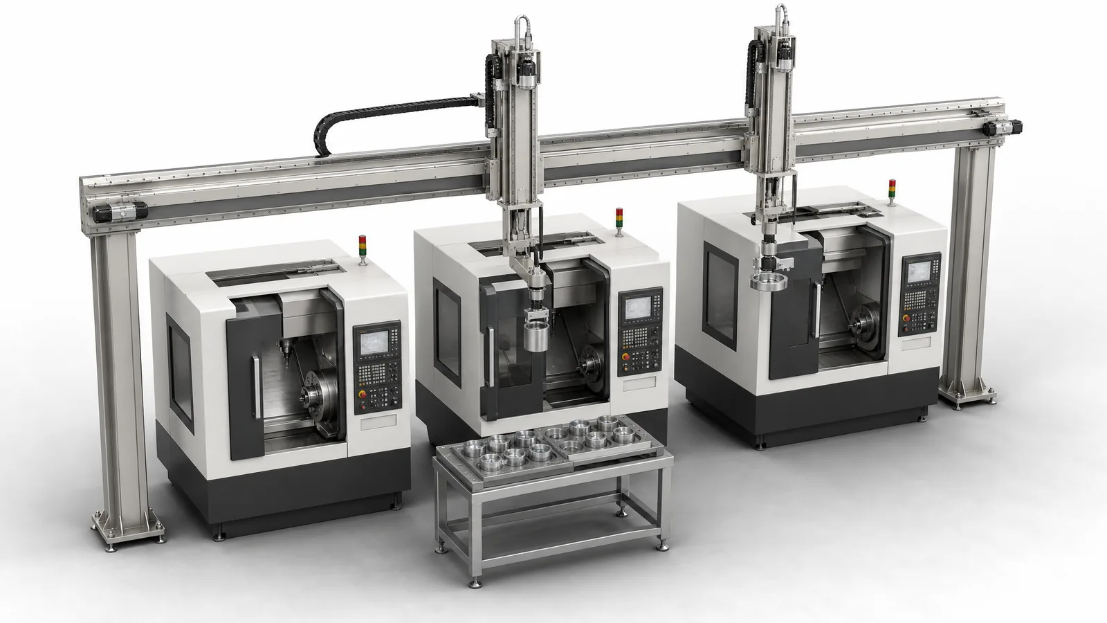
Motionwell Automation designs and builds machine tending automation in Singapore, the automated loading and unloading of production machines. Machining centres, lathes, presses, testers and moulding machines are all tended this way, and our delivered work sits at two ends of that range, metalcutting machine tools and test instruments. The reference at the heavy end is our own linear gantry robot series, where a steel single-beam gantry running the length of the row with dual Z-axis heads services more than ten CNC machines in parallel, one Z axis lifting finished parts out while the other puts blanks in.
The series runs from a compact three-axis aluminium extrusion frame with pneumatic multi-finger grippers, through welded steel single-beam builds, to double-beam bridge gantries on multiple columns for the heaviest parts and the widest spans, with payload, travel and repeatability sized per build against your parts and your row. Machines are designed, assembled and tested at our Woodlands Link facility, and the company has delivered more than 150 special purpose machines since 2014 under ISO 9001:2015 and bizSAFE Level 3.
What we build is the gantry, the tooling, the part presentation, the machine interface and the control system that ties them together. Our mechanical designers have direct experience operating CNC machines, which keeps out designs that look good on screen and are impractical to manufacture. The delivered gantry work sits in context on our warehouse and intralogistics page.
Which Robot Type Should Tend Your Machines?
Three families cover almost every robotic machine tending cell you will be quoted, and three measurements settle the choice before anyone opens CAD: how far the robot must travel, how much floor you can give it, and how many machines it has to serve. We build the gantry and integrate industrial and collaborative arms from the major platforms, including arms you have already bought.
| Selection factor | Linear gantry | Articulated six-axis arm | Collaborative arm |
|---|---|---|---|
| Machines served per unit | Ten or more on a straight row | One or two within reach, more on a seventh-axis track | Usually one |
| Travel | Set by the row: X is built in joinable sections, so travel is a structural choice | Reach-limited unless extended on a linear track | Short, sized around one machine |
| Floor space | Travels overhead, so the floor stays clear for operators and pallet trucks | Its own cell area plus access | Small footprint, shared with the operator |
| Payload | Set by the structure class, and held across the travel | Falls off sharply at full extension | Rated payload minus the gripper, less again at reach |
| Orientation freedom | Three axes, so the part enters as the gantry presents it | Full six-axis, which suits an angled chuck or tilted fixture | Full six-axis, at low speed |
| Where it fails | A scattered layout, or a part that must enter at an angle | Long rows, because reach is the wrong tool for distance | Rate, and payload once the gripper is counted |
The first row decides most projects. An arm is bought for orientation freedom and pays for it in reach; a gantry is bought for distance and pays for it in orientation. If your parts drop vertically into a chuck and your machines sit in a line, you are paying for articulation you will never use. If the part enters an angled fixture, no amount of gantry travel substitutes for a wrist. Presenting a nozzle to a curved surface is the same problem, worked through on our aerospace surface treatment automation page.
Collaborative arms earn their place where the duty is one machine, the part is light and a person is genuinely in the loop. Our delivered cobot tending is test and laboratory work: a cobot loads universal testing machines in the QA laboratory automation programme re-ordered in four consecutive years, and another loads specimens into the enclosure on our cleanroom automated test equipment, holding ±0.05 mm at the fixture interface. A force-limited arm is slow by design, and that slowness compounds across every machine it reaches.
Why Does One Long Gantry Beat Several Arms on a Row of Machines?
Distance is cheap on a beam and expensive on a wrist, and the machines already sit in a line for reasons that have nothing to do with robots.
A gantry extends along X in sections, so a longer row may be served by extending the beam and rail instead of adding a separate robot cell. Check the longer route’s cycle time, supports, drive capacity, cable carrier and protective perimeter. Overhead travel can preserve useful floor access, while the load path and maintenance access still need their own assessment. An articulated arm can also gain travel through a linear axis, as compared in our gantry versus six-axis guide.
The cost argument is an engineering trade, not a discount. Where a row of machine tools is served by one overhead gantry, both the capital and the fenced cell area come out below what several six-axis arms cost for the same job, because you buy one motion system and fence one perimeter. That reverses the moment the machines stop being in a row: a scattered layout, machines on both sides of an aisle, or a part that must be reoriented between operations all push the answer back towards arms.
| Series | Structure | Where it sits in the range | Z axes | Where it fits |
|---|---|---|---|---|
| Compact three-axis | Aluminium extrusion frame, bolted and light | Lightest parts, shortest travel | 1 | Light parts, small machines, transfer between assembly stations |
| Steel single beam | Welded steel structure, beam built in sections along X | Heavier parts along a row of machines | 1 or 2 | A row of CNC machines, ten or more tools from one gantry |
| Double beam | Twin-beam bridge on multiple columns, with maintenance walkway and railings | Wide spans and heavy workpieces, where one section can no longer take the bending and the twist together | 1 or 2 | Heavy workpieces, wide spans |
Payload, travel and repeatability are outputs of a build, not properties of a series: they follow from the section depth, the column spacing, the stroke and the moving mass once your part and your row are known, which is why the boundaries above are written as construction. Traverse speed moves the other way as the machine grows, because the longer the axis and the heavier the moving mass, the more it costs to stop that mass inside a safe distance, so the largest builds in the range are not the fastest ones.
Two design points inside that table matter more than the class name.
Dual Z axes. The single-beam and double-beam builds can carry two independent Z columns, each with its own gripper pair. One column lifts the finished part out while the other lowers the next blank in, so load and unload happen in one visit instead of two. Across a row of machines that halves the number of visits, and it is the visits that limit how many machines one gantry can hold.
Repeatability is not placement accuracy. A gantry’s repeatability figure tells you nothing about whether the part seats in the chuck. Seating is decided by how well the blank was located before the pick, by gripper repeatability, by chip on the locating face and by fixture wear. Where a blank cannot be located mechanically, a camera measures its actual position before each pick and the controller corrects the move, the approach set out on our machine vision inspection page.
What Does the Machine Tool Have to Tell the Robot Before It Can Be Loaded?
Which arm to use is the wrong argument to have first. What decides a tending cell is whether the machine tools can hand over a confirmed door and chuck state, and an arm picked before that is known has been picked on the wrong information. The signal list below is the foundation the rest of the cell is designed on, because a robot cannot tend a machine that cannot talk to it. The machine has to say that it has finished, that the door is open and that the workholding has let go, and it has to hold still while steel is in its work envelope.
| Signal | Direction | What it means | What goes wrong without it |
|---|---|---|---|
| Cycle complete | Machine to robot | The programme has ended and the spindle has stopped | The robot enters on a timer and meets a moving tool |
| Door open, confirmed | Machine to robot | The door has physically reached the open position | The gripper hits a door that stuck halfway |
| Chuck or vice open, confirmed | Machine to robot | Workholding has released, sensed | The robot pulls against a clamped part and drops it or wrecks the tooling |
| Part present or clamped | Machine to robot | A part is in the fixture and gripped | The machine cuts air, or the robot loads onto a part still there |
| Robot in envelope | Robot to machine | Hold the machine: no motion, no door close | The door closes on the arm |
| Cycle start | Robot to machine | The envelope is clear, begin the programme | Someone has to press a button, so nothing runs unattended |
A fault and mode signal in both directions belongs on that list too, so the cell stops feeding a machine that has already stopped. Newer machine tools generally offer a robot interface option, providing most of it as a defined connector and a set of auxiliary functions, usually programmed as spare M-functions in the part programme. On an older machine that option often does not exist and the interface has to be added. Do that through the machine tool builder or their agent wherever possible. The door interlock and the chuck clamp are safety functions on that machine, so taking control of them moves responsibility onto whoever did the work, and a modification substantial enough can put that party into the manufacturer’s position for the modified machine. Our machine safety and CE marking page works that through.
The control-side half is routine here. Control system modernisation of legacy machines, replacing ageing PLCs, servo drives and VFDs, is our largest line of work this year. Which control platform the replacement lands on is normally your plant standard, and that is the right way round: the spares cupboard, the maintenance team’s training and the local service agent all sit with the platform, and none of them moves because one new cell arrived. Where a controller is too old to extend safely we quote the replacement, with no second one bolted alongside it.
After a control retrofit, repeat the tending permissions and clamp/door interface tests. CNC retrofit tending interface includes these checks with the machining acceptance.
How Should Parts Be Presented to the Robot?
Part presentation decides how much the robot has to work out for itself before it picks, and that is what sets the sensing, the tooling and the cycle time around it. The feeders and escapements that do that work are covered on our part feeding and presentation page, and the head-to-head against an articulated arm on gantry versus six-axis machine tending.
| Presentation | How the robot finds the part | Suits | What it costs you |
|---|---|---|---|
| Bar or billet magazine | Mechanical, one part at a time at a fixed pick point | Turned parts, repetitive blanks of one size | A magazine per blank size, and a jam clears by hand |
| Fixtured tray or pallet | Taught grid, indexed by row and column | Machined blanks, medium mix, batch running | Trays are a real cost per part family, and someone loads them |
| Conveyor with stop and locate | Driven against a stop and squared before the pick | Continuous feed from an upstream process | Needs presence sensing and a squaring device |
| Random bin | Nothing is known until a 3D sensor measures it | High-mix unsorted castings and forgings | A different project, see below |
The first three share one property: position is engineered before the robot arrives, by a fixture or by a locating motion. That is why they are predictable to quote, and why position is confirmed by a sensor at the pick point. A timer cannot tell a blank that is missing from a blank that is late, and a gripper closing on nothing costs a cycle at best and a collision with the chuck at worst.
Tooling follows the part. The compact three-axis frames in our linear gantry series run pneumatic multi-finger grippers, and the truss manipulators run pneumatic grippers sized to the load; where a second tool has to fit without re-machining the Z column we design a quick-change interface in. For mixed part families, changeover frequency decides between one combination tool that compromises on every part and a tool rack: several changes a shift argues for the combination tool, weekly changes argue for the rack. Gripper bodies and pneumatics are bought as catalogue items and the application tooling, meaning the fingers, the nests and the sensing that proves the grip, is designed in house. The split is deliberate: the catalogue half has distributor stock and a defined replacement path anywhere in the region, and the half that decides whether your blank seats in the chuck is the half nobody can specify for you from a datasheet.
Different tending tools can require different payloads and machine permissions. machine-tending tool changes tests tool identity and interrupted exchanges before resuming motion.
A tending cell needs a confirmed correctly presented workpiece. magnetic tending grippers tests the magnetic pickup, multiple-sheet detection and release into the machine.
Why Is Bin Picking a Different Project?
Everything above depends on the part’s position being known before the robot moves, and a random bin removes that assumption. From a bin the robot has to perceive the scene, choose a part that is on top and reachable, plan a collision-free approach into a steel container, grip a part whose orientation it did not choose, then place it in a known orientation, which usually means a regrip station. That last step catches people out: picking successfully from the bin does not put the part in the chuck the right way round.
Motionwell’s delivered picking is from fixtured, taught or vision-corrected positions, where that geometry is settled before the robot arrives. Parts that genuinely arrive heaped are a perception project on top of the motion project, needing its own proving trial on your actual castings, and the first thing worth costing is whether tray or magazine presentation upstream comes in below perception downstream. Very often it does.
What Do Swarf, Chips and Coolant Do to a Tending Cell?
They are the environmental problem that decides whether the cell still runs in year three, and they are consistently under-scoped. Four places take the damage.
The mechanism takes it first. Linear guides, ball screws and rack teeth collect chips, and coolant mist strips the grease off them. This is one of the arguments for overhead travel: the structure sits above the mess. Where the environment is genuinely dirty we specify V-groove roller guides, which is what our dual-rail truss manipulators run in dusty and harsh service, because a roller on a V edge sheds the debris a ball guide would ingest.
The cabling takes it next. Every gantry axis carries its cables in a cable carrier, and a carrier filling with hot chips becomes an abrasion problem long before it becomes a jam. Route it away from the chip conveyor discharge and specify continuous-flex cable rated for the travel.
Then the gripper and the part. A chip on a locating face is a common cause of a part that will not seat, and it is invisible on a drawing. The fixes have to be designed in: an air blast at the chuck and at the gripper before every load, a locating scheme that seats on features a chip cannot sit on, and a clamp confirmation that measures instead of assuming. Coolant carried out on a wet part is also a floor hazard and a gripper slip risk, which is why a drain and dwell position on the way out earns its cycle seconds.
The sensors take it last, and quietly. Optical devices under a coolant film report whatever they like, so inductive sensing is the safer choice on metal parts in a wet environment.
How Does the Cycle-Time Arithmetic Actually Work?
Machine tending is the one application where an idle robot is the correct outcome, and misreading that is a common reason a sound project gets rejected.
Separate station service time from travel. Station service includes the door and chuck handshakes, reach-in, removal, blank placement, withdrawal, door close and cycle start. Travel is the movement between stations. A dual Z-axis head combines removal and loading in one visit.
Initial machine-count estimate ≈ shortest machining cycle ÷ (station service time + average travel time per stop)
This is a rough screening calculation for a repeating row with similar service times, not the final schedule. Count travel once, include the return route and check when each machine will actually be ready. A sequence simulation should account for unequal machining cycles, overlapping door motion, buffer positions and recovery. Longer machining cycles leave more time to share one handler across the row.
What Does Unattended Running Actually Demand?
Running with nobody watching is a different specification. Five things have to be true, and each is a cost.
Enough material in, and enough space for parts out. The cell runs until the input empties or the output fills, so magazine depth and finished-part buffer, measured in minutes at your cycle rate, are specifications worth writing down. This is what quietly decides how many unattended hours you get, and downstream the same handling engineering continues into automated palletizing for finished parts.
Defined fault detection and response. Monitor part presence, grip confirmation, chuck and door states, tool life, coolant, chip handling and air pressure as required by the process. Challenge missing, contradictory and stuck signals during testing, and define the hold or stop state for each identified fault.
A defined behaviour on every fault. Stop and hold is the right default. Where a fault is transient a bounded retry beats an immediate stop, and it must still be logged. We use that pattern in the QA lab cell, where each positioning layer retries its tolerance check up to three times before escalating with the failure mode recorded, on the reasoning that a fault recovered silently is worse than a stoppage.
A record of what happened while nobody was there. Counts and timestamped alarms, so the morning shift can tell whether the cell stopped at 22:15 or 05:50. That difference is a night of spindle hours.
Guarding that holds with nobody in the room. Unattended running does not reduce the safety scope; it changes who carries the residual risk, because whoever opens the guard next arrives at a cell in an unknown state. Restart should need a deliberate reset with a view of the whole cell, never a power cycle. We have delivered cobot-assisted loading for unattended operation on the 5-axis CNC shot peening machine built for turbine blade surface treatment.
What Safety Scope Applies to a Machine Tending Cell in Singapore?
Start from an ISO 12100 risk assessment and let it drive the design. A tending cell carries a specific hazard mix: a robot moving over long travel, a machine tool with its own energy sources, a door that closes, workholding that clamps with real force, and an operator who reloads magazines and clears chips while the cell is live.
ISO 10218-1 covers the robot and ISO 10218-2 the integrated system, which is the part a machine builder owns. Each safety function then carries a required performance level under ISO 13849-1, calculated and validated. The 2025 edition of ISO 10218-1 is current and the first substantive revision since 2011; it references the 2023 edition of ISO 13849-1, so a design documented against the older edition will need its performance level calculations restated when the cell is reassessed.
Three points specific to tending are worth settling before layout is fixed. The boundary between two safety systems: the machine tool has its own door interlock and stop category and the cell has its own, so somebody must own the boundary and prove the robot cannot enter while the spindle can turn. Stopping performance after a retrofit: measure real stopping time, then confirm the scanner distances calculated to ISO 13855 still hold, because a new servo drive on old mechanics changes run-down time in ways no datasheet predicts. Local requirements: Singapore does not require CE marking, but the Workplace Safety and Health Act requires dangerous parts of machinery to be securely fenced, and machines incorporating lifting equipment must be certified by an approved authorised examiner before use.
We deliver the physical scope that follows: guard fencing and interlocked access doors, safety laser scanners, safety-rated stop circuits, LVD and CE testing, and MOM lifting certification. For a collaborative arm, validate the selected operating mode with the real gripper and blank. Sharp or heavy loads may make contact unacceptable and call for protective separation, monitored stops or guarding, as our note on collaborative robot safety standards explains.
What Drives Cost and Lead Time on a Machine Tending System?
Machine tending cost includes the handler, tooling and the work needed to connect each machine. Surveying undocumented legacy circuits can be a substantial part of the interface and safety scope. Time the door, chuck and ready signals on the actual machines, because those waits can exceed the robot travel time. Our guide to what OEE actually measures explains how this affects utilization. The remaining cost drivers are listed below.
| Cost driver | Why it moves the number |
|---|---|
| Machine count and row length | Sets beam length, rail, cable carrier and drive sizing, and it is the cheapest thing to get right at concept |
| Single or dual Z axis | A second Z column is a second set of drives and tooling, bought back in trips saved per machine |
| Part family count | Each family is a gripper, a fixture, a tray and a recipe; format count costs more than it looks |
| Part presentation | A magazine or fixtured tray is engineering you can price; perception into a random bin is a project |
| Machine interface state | A robot-ready machine tool is a connector; a legacy row is an interface per machine |
| Safety scope | Perimeter length, access points, scanner zones, and stopping performance measurement after retrofit |
Lead time runs 16 to 24 weeks from concept approval to factory acceptance testing on a standard build, and 24 to 32 weeks where cleanroom compatibility or full validation documentation applies. Design, fabrication, assembly and testing happen at Woodlands Link with an in-house design team of eight, which is why a Singapore buyer attends the factory acceptance test without flying to it. That matters on tending work, because the adjustments that decide whether a cell runs are gripper and fixture details found on your own parts. How a build of this shape is scoped and commissioned is covered in our special purpose machine design guide.
Standards Used in Machine Design and Validation
These references inform the design, testing and documentation described on this page. Each row links to its primary source and records the edition checked.
| Standard | Current edition | What it means for your machine |
|---|---|---|
| ISO 10218-1: Robotics, safety requirements, Part 1: industrial robots | ISO 10218-1:2025 | Published February 2025, the third edition and the first substantive revision since 2011. It adds robot classifications with matching functional safety requirements and safety-related cybersecurity requirements. Most of ISO/TS 15066:2016 on collaborative operation moved into Part 2.Checked 12 Sep 2026 against ISO 10218-1:2025 (iso.org/standard/73933.html) |
| ISO 13849-1: Safety of machinery, safety-related parts of control systems | ISO 13849-1:2023 | Provides the design method for safety-related control functions, including architecture, component reliability, diagnostic coverage and common-cause failure measures. The machine risk assessment establishes the required Performance Level; design calculations and validation provide the evidence for each function.Checked 1 Sep 2026 against ISO 10218-1:2025 normative references |
Frequently Asked Questions
How many machine tools can one gantry robot serve?
Our delivered steel single-beam systems with dual Z-axis heads have served more than ten CNC machines. The achievable count depends on station service time, travel and the machining cycle at each stop. Use a round-trip timing check for the initial layout, then simulate the actual sequence, including unequal cycles, door and chuck handshakes and recovery. A short-cycle machine can need a different schedule or a dedicated handler.
Do I need to modify my CNC machine to add a robot?
Almost always, if the machine is more than a few years old. The robot needs the machine to tell it that the cycle is finished, that the door is open, and that the chuck or vice has actually released, and it needs to hold the machine while a tool is inside the work envelope. Newer machine tools generally offer a robot interface option providing those signals. Legacy machines usually need an interface added, and the safe route is through the machine builder or their agent, because the door interlock and the clamp are safety functions on a machine that was signed off without you.
Is machine tending worth automating if the robot waits most of the cycle?
Yes, and robot idle time is the wrong metric. A tending robot is bought to take an operator off a repetitive load and unload task and to keep the machine cutting through breaks, shift changes and the night. On a long machining cycle the robot is idle by design, and that idle time is exactly the headroom that lets one gantry cover a row of machines instead of one. Judge the investment on machine utilisation and on spindle hours run unattended.