
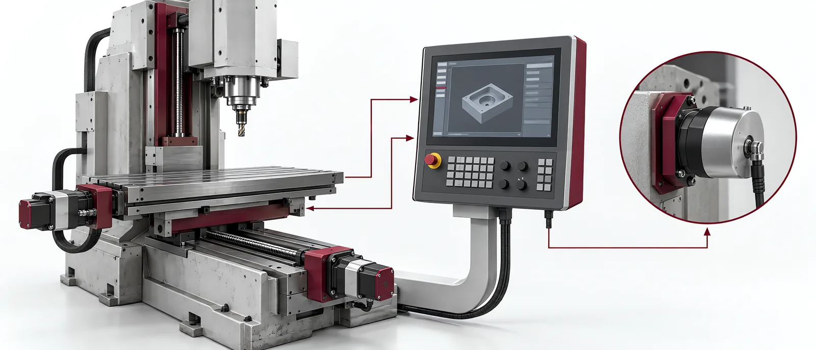
Conceptual equipment illustration.
A CNC control retrofit replaces or modernizes the control system while establishing which existing machine components remain usable. Start with the machine functions and interface inventory. The mechanical condition, drives, feedback devices and auxiliary systems determine more than the appearance of a new operator panel.
The project belongs within machine retrofit and modernization, with a machine-specific acceptance plan.
Separate Retained Hardware from Compatible Hardware
List axis motors, drives, encoders, spindle control, tool changer, probing and machine I/O. Record their actual types and interfaces. A retained motor is not necessarily compatible with the proposed drive, and an encoder connector does not establish its signal protocol.
Siemens’ machine-tool retrofit overview describes evaluation, component integration and commissioning. Use that workflow to establish the specific replacement boundary; do not infer that every original component can be reused.
The servo-drive retrofit scope covers axis-level compatibility. Make any replacement motor, feedback or drive explicit in the quotation so that it is not hidden behind “new CNC control”.
Rebuild the Machine Sequence
Map homing, limits, spindle permissions, lubrication, clamping and tool-change states. Confirm how the CNC and machine PLC divide these functions. A machining programme can be correct while an auxiliary interlock remains incomplete.
If the project also replaces a separate controller, coordinate the PLC migration with the CNC configuration. Keep the completed I/O and interlock map with both systems.
Test manual operations, automatic cycles and interrupted states. A tool change stopped halfway needs a known recovery position and state; resuming from the next programme line may not represent a valid mechanical condition.
Accept the Machine on the Required Work
Distinguish motion checks from product checks. Verified reference positions and axis travel establish part of the configuration. A representative finished workpiece establishes whether the configured machine performs the manufacturing task under the agreed conditions.
Record tooling, material, programme and measurement method with the workpiece result. A comparison is useful only when its inputs are stated. Do not borrow a supplier’s reported cycle-time improvement as a forecast for a different machine.
For a machine using automatic loading, repeat the interface test with the machine-tending system. Door, clamp and machining states must agree across the two systems.
Preserve the Maintainable Configuration
Handover should identify CNC/PLC software, drive settings, backups and the final electrical drawings. Retained and replaced equipment should be identifiable for future maintenance.
Contact Motionwell about the CNC machine to discuss the control boundary, retained hardware and workpiece test.