
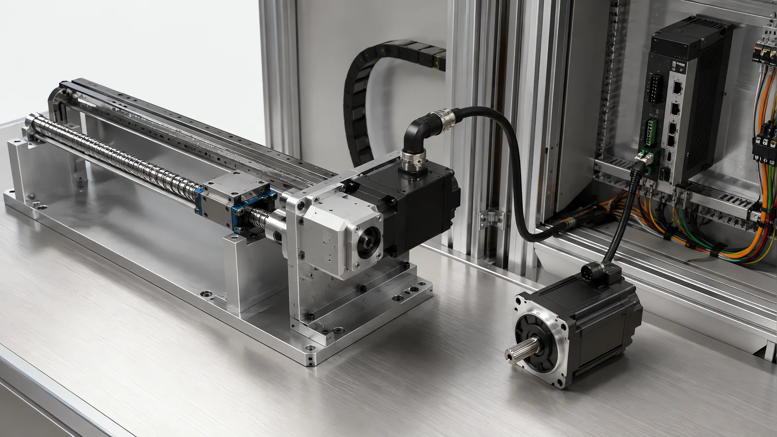
Motionwell Automation does servo retrofit and industrial drive replacement in Singapore inside our largest line of work this year, control system modernisation of existing production machines: replacing ageing PLCs, servo drives and VFDs on machines whose frames, screws and guides are still sound. The platform those replacements land on is the plant’s decision more than ours, because every extra control platform on a shop floor is another set of spares to hold, another licence to renew and another call-out number to find at two in the morning. The motion half of that work is industrial drive replacement on an axis whose frame, guides, screw and gearbox are staying exactly where they are.
Machines are designed, assembled and tested at our Woodlands Link facility, and the company has delivered more than 150 special purpose machines since 2014 under ISO 9001:2015 and bizSAFE Level 3.
The short version comes first. The mechanics of a well-built machine usually outlast its electronics, which is the whole reason this work exists: you are buying a second service life for a frame, a screw and a set of guides that are already paid for. A drive retrofit buys two things reliably, adjustability and data, and one thing conditionally, which is rate. It will not repair worn mechanics, and a stiffer position loop closed around a worn mechanism tends to expose the wear.
A word on scale, since the axis count is the first thing a buyer reaches for. Seven axes is a normal size for this work, and on an indexer that means the indexer arms plus a rotary station, each axis getting a matched drive, motor and combined power and encoder cable while the mechanism, frame and tooling stay exactly where they are. Two things inside that scope matter more than the axis count. Moving field I/O out to distributed blocks at the machine, on a dual-port industrial ethernet connection, is what turns a motion replacement into diagnosable motion, because a fault that names the block and the point is a fault somebody can go straight to, where one that reports only a stopped machine sends a technician round the panel with a meter. And the number that matters at survey is not the axis count but how many of those axes are holding a load, since those decide the brake and the stored-energy questions covered further down.
The axis is re-engineered around catalogue motors, drives, encoders, gearboxes and cable on whichever control platform your plant already runs, and which platform that is gets settled before the drives are selected. Two boundaries decide which page you should be reading. If the controller has run out of support, that is a different project, on our PLC migration and upgrade page. If the axis does not exist yet and has to be designed from a mass, a stroke and a move time, that is new-build work on our servo lift and precision positioning page. The motor-selection argument in general form is in our note on servo and stepper motor drives.
Why Do a Machine’s Mechanics Usually Outlive Its Electronics?
The two age against different clocks, and only one of them is under your control.
A frame, a set of linear guides, a ballscrew and a gearbox wear in proportion to use, in ways a maintenance schedule can measure and stay ahead of, so the mechanism degrades slowly and visibly. Electronics do not fail that way. A drive can be in perfect working order and still be unsupportable, because the part number is out of production, the programming software will not install on a current operating system, or the last engineer who knew the machine has retired. None of that shows up in a vibration reading.
That gap is what we see across the retrofit work: much of it has a compliance or supportability driver, and the machine still runs fine while its control system cannot do something the plant now needs. The second driver is adjustability. A cam-driven axis is not adjustable, so a new product variant becomes a machining job, while a servo with an electronic cam profile turns it into a recipe change. That is usually the whole business case, ahead of any speed gain.
| What the machine is made of | What ends its life | What the ending looks like on the floor |
|---|---|---|
| Frame, castings, columns | Fatigue and impact damage, rarely reached in normal service | Nothing, on most machines, for decades |
| Linear guides, ballscrews, racks | Wear against use and contamination, measurable and correctable | Growing backlash, lost motion, noise at reversal, drifting repeatability |
| Servo amplifiers, DC drives, VFDs | Component ageing plus vendor support and spares availability | A failure that cannot be replaced like for like, so the machine stops for a purchasing decision |
| Feedback devices and their cabling | Flex fatigue, contamination, connector wear | Intermittent faults that move when the cable is disturbed |
| The knowledge of how it works | People leaving and drawings not being updated | Nobody can say what the existing circuit does |
Read the last row as a cost item. On legacy machines the control system is often undocumented, and working out what the existing circuits do before replacing them is frequently the largest single item in a retrofit safety scope.
How Do You Match a New Motor and Drive to a Mechanism You Are Not Changing?
This is a part quotations get wrong, and the trap is that torque is the number that gets checked first. A modern motor rated for the same continuous torque as the one it replaces is often not the same physical object, because a frame sized for a given continuous torque today is commonly shorter and lighter than the one it replaces, which changes the shaft diameter, the keyway, the flange pilot, the bolt circle, the length behind the mount and the position of the connectors.
The mechanical fit is therefore a drawing exercise before it is a catalogue one, and it usually resolves into an adaptor plate, a coupling bored to the new shaft, and a check that the motor still fits the space the guard leaves. None of it is difficult, and all of it is expensive to discover during the shutdown.
Rotor inertia is worth pulling out of the list, because it is invisible on a nameplate comparison and it decides how the axis behaves afterwards. The ratio between the load inertia reflected to the motor and the rotor’s own inertia is what makes an axis tuneable, and a smaller, lighter rotor on an unchanged load raises that ratio. A gearbox is the lever that fixes it, since a ratio reduces reflected load inertia by the square of the ratio, which is what makes a large mass controllable by a small rotor. Changing that ratio is a decision about top speed at the same time, and the resolution is usually the motion profile.
| What has to line up | What to check before ordering | What it costs if you find it during the shutdown |
|---|---|---|
| Continuous and peak torque at the operating speed | The torque-speed curve at the point the axis actually works | An axis that faults on acceleration with a full load |
| Rotor inertia against reflected load inertia | Load inertia through the existing gearbox and screw lead, against the candidate rotor | An axis that will not hold gain, so settling gets slower |
| Shaft, keyway, flange pilot and bolt circle | The old motor drawing against the new one, plus the coupling or pulley bore | An adaptor plate and a coupling machined under time pressure |
| Envelope behind the mount | Overall length, connector orientation and bend radius inside the guard | A motor that fits the flange but not the machine |
| Feedback type | Resolver, incremental or absolute serial, and which drives support it | Motor and drive have to be bought as a matched pair, so a mismatch means re-ordering both |
| Motor and feedback cable | Continuous-flex rating for the travel, length limits, screening | Intermittent faults nobody can reproduce, on a cable reused to save a day |
| Panel space, supply and heat | Physical space, incoming supply arrangement, heat load in the enclosure | A cabinet rebuild that was not in the scope |
Two habits save most of this. Record the nameplate of every motor and drive before quoting anything, including the ones nobody plans to touch, because a machine rarely carries one generation of hardware. And treat existing cable as suspect, since a cable that has flexed in a carrier for years is cheap to renew and expensive to diagnose. Where the panel is rebuilt around the new drives, name EN 60204-1 in the scope so the rebuild is not quoted as like-for-like rewiring.
For the communication part of the replacement, the EtherCAT vs PROFINET guide separates drive timing, controller tasks and network capability. Confirm the motor and feedback dependencies before attributing an axis limitation to the fieldbus.
Axis drive compatibility is one part of a CNC replacement. CNC retrofit interfaces connects feedback, machine auxiliaries and representative machining tests.
What Actually Changes When You Gain Absolute Position Feedback?
More changes than the homing routine, which is the part everyone expects.
An incremental device counts from wherever it was switched on, so the machine must find a datum before it can be trusted, every time; an absolute device knows its position at power-up. On long gantry and track axes we specify servos with absolute encoders for exactly that: it removes the homing routine, holds position knowledge after a power loss, and supports dual-motor gantry synchronisation.
The operational change is in recovery. A machine that has to home cannot resume after a stop mid-cycle until it has been cleared, which on a legacy machine means a person opening a guard and taking a part out of a fixture by hand. On a vertical axis it matters more again, because homing a suspended load means moving it while nobody yet knows where it is.
| Incremental feedback | Absolute feedback | |
|---|---|---|
| After power-up | Home before the machine can be trusted | Position known, no datum move |
| After a stop mid-cycle | Clear the machine, then home, then resume | Resume from where it stopped, subject to the process allowing it |
| What holds the reference | The homing sensor, its repeatability and its mounting | The encoder, plus the offset stored in drive parameters |
| After mechanical work on the axis | Re-home, which the machine does anyway | Re-establish and re-record the offset deliberately |
| Multiturn position with power off | Not applicable | Retained by battery-backed counter or a geared stage, whichever the device uses, and it becomes a maintenance item with an owner |
| Where it earns its cost | Short axes that home against a hard stop harmlessly | Long axes, vertical axes, coordinated pairs, any axis that must recover without a person |
One consequence follows from the third and fourth rows. The reference that used to live in a sensor bracket now lives in a parameter file, so the parameter backup becomes the thing that lets the machine be repaired. Somebody has to own it, and it has to be re-made after every commissioning change.
Is a VFD Enough, or Does the Axis Genuinely Need a Servo?
That question is worth asking per axis, because converting everything that spins into a servo is how a retrofit scope doubles without buying anything useful. Where an axis has no positioning requirement, an induction motor and a VFD is the cheaper right answer, and a general-purpose drive covers a fixed-speed conveyor or pump without adding a tuned axis to the machine’s maintenance list.
The line is drawn by what the axis has to prove. A VFD controls speed and, with a vector mode and a feedback device, torque. What it does not give you is a repeatable stop position, a profile that changes by recipe, coordination with another axis, or a position the controller can verify. When any of those four is in the requirement, the axis has become a servo axis whatever it used to be.
| Axis on a legacy machine | What to fit on the retrofit | What actually changes |
|---|---|---|
| Fixed-speed conveyor, pump, fan, mixer | Induction motor and VFD | Speed becomes adjustable and starts become soft; the mechanism is untouched |
| Indexing table or transfer, currently cam-driven | Servo | Dwell per station becomes a recipe, and the index is verifiable |
| Dosing or fill head on a mechanical linkage | Servo | Volume becomes a function of commanded stroke, so a format change stops being a fitter’s job |
| Long travel or gantry axis with a DC drive | Servo, absolute encoder | Homing goes away, position survives a power loss, and paired motors can be synchronised |
| Press or insertion station | Servo | Force and position are logged together as the process record |
| Two-position clamp, gate, stop or ejector | Leave the air alone | Nothing, which is the point; a cylinder with reed switches is already the right answer |
| Light, low-duty adjust axis | Stepper or closed-loop stepper | Cheap to convert, and it does not pretend to be a positioning axis |
The row that saves money without buying anything is the last-but-one: an electric axis bought to replace a working cylinder buys tuning, cabling and a parameter backup for a move with two ends. The same argument on a filling machine, where a controls retrofit is often the cheapest accuracy improvement available on mechanically sound equipment, is on our drum and pail filling page.
Why Is Tuning the Hard Part on an Old Mechanism?
A servo axis cannot be tuned stiffer than the structure and transmission it is bolted to, and an old mechanism has more compliance and lost motion in it than the drive’s autotune expects to find.
The reason this bites on retrofits specifically is what the old control did. A cam defines motion geometrically, and a DC drive behind it only had to keep the speed roughly right, so backlash in a worn gearbox, a stretched belt, lead error in a screw and wind-up in a coupling were all tolerated because nothing closed a tight position loop around them. A modern drive does close that loop, at a bandwidth the mechanism has never been asked to accept, and the mechanism answers by ringing.
Four responses, in the order they are worth trying:
Lower the gains and accept the settling time. That costs nothing, and it tells you how much of the machine’s performance was hiding in its mechanics. Autotune gets most of the way; the last part is manual.
Approach every station from the same direction. A single-direction approach takes most of the backlash error out for the price of a little extra travel, and where an axis indexes between fixed stations it often costs nothing at all.
Filter the resonance in the drive. Notching out a narrow structural resonance raises the useful gain. It does not touch lost motion, and a filter used to mask a mechanical fault keeps working right up to the point the fault gets worse.
Then fix the mechanism: replace the worn gearbox, preload the rack, change the screw. That is a different budget, and it belongs in the quotation as its own line.
State the tuning result the way it will be used later. Gains, filters and profile limits have to be restorable after a drive is swapped at two in the morning, and they live in the same parameter file as the encoder offset.
What Do You Gain From New Drives That Is Not Motion?
You gain a condition monitor on every axis you convert, at no extra hardware cost. A servo drive computes torque and following error every control cycle because it needs them to work, and once the controller can read them, the machine is measuring itself on every move it makes.
That is how we design assembly machines in the first place. On a multi-station rotary assembly machine, a 12-station dial for example, we would put a load cell on every press-fit station and record the full force-displacement curve against the part identity, so a fault is attributed to the station that caused it; the design reasoning is on our page on how we design multi-station rotary assembly machines. How that generalises to measurement is on our inline dimensional measurement page.
On a retrofitted axis the same signal points at the old mechanics. The torque needed to make an identical move on an identical load measures what the mechanism is doing, and a trend that climbs over months is a guide, a screw or a belt telling you something quietly. Following error does the same job from the other side: a jam grows the error until the drive faults the machine with a code and a number, never in the silence an open-loop axis fails in.
Two things separate data from disk usage. Somebody has to look, so agree at scoping who reads the trend and what they do when it moves. And the alarm structure gets rebuilt during a retrofit anyway, which is the moment when tagging each alarm with a loss category costs almost nothing, so downtime arrives already sorted; the method is in our note on measuring OEE in production. Doing it two years later means touching a program that is by then in service.
One caution comes attached. A machine that ran for fifteen years with no network port suddenly has an EtherNet/IP switch, a data path to a plant server and an engineer who would like to dial in from home. Keep the controller, drives and I/O on their own segment with no route outward, put anything that talks upward on a second interface, and decide the remote access policy before commissioning, as set out in our guide to IEC 62443 for industrial control systems.
Those diagnostic values need a supported route into the controller or monitoring system. Check the exact drive and controller combination: our industrial Ethernet comparison separates basic connectivity from supported motion and diagnostic functions.
What Holds the Load When the New Drive Loses Power?
On a vertical axis the load is held by whatever is mechanical, because the new drive holds nothing at all once power is removed.
This matters more on a retrofit than on a new build, because the old machine may have held its vertical axis in a way the replacement does not reproduce. A self-locking worm, a low-lead screw or a brake integral to the old motor all disappear the moment somebody specifies a more efficient transmission or a motor without a brake option.
Read three figures off the new motor’s datasheet before assuming the brake covers it: static holding torque against the gravity load with the heaviest tool fitted, permitted braking energy and number of emergency stops, and engagement delay, because the gap between the drive dropping torque and the brake gripping has a distance attached to it. Whether that brake is a machine component or a rated safety function is an output of the risk assessment, and the full treatment of holding torque, counterbalance and power-loss testing is on the servo lift and positioning page.
Define the stop sequence for each axis and its load. Safe Torque Off prevents the drive from producing torque; controlled deceleration, holding brakes or other load-retention measures may also be needed to reach and maintain the required safe state. The test plan covers emergency stops, supply loss, brake engagement and restart under representative loads. Measured stopping time and distance then support the safeguarding layout.
Which Mechanical Conditions Should the Retrofit Survey Measure?
The findings below are the kind that turn into change orders, and they are cheaper to find with a dial indicator during the survey than with a commissioning engineer during the shutdown.
| What shows up after the retrofit | A common cause | What to check before ordering drives |
|---|---|---|
| The axis rings or overshoots at gains the autotune chose | Structural compliance or a stretched belt setting the ceiling on useful gain | Move the axis by hand at the tool point and feel for deflection and lost motion |
| Following-error faults on acceleration with a full load | Reflected inertia against the new rotor, or a mechanism stiffer to move than the old drive ever revealed | Measured breakaway and running torque on the existing machine, and the load inertia through the actual ratio |
| Repeatable in one direction, scattered in the other | Backlash in a gearbox, rack or nut, taken up one way only | Dial indicator at the tool point, reversing under load |
| Continuous high current with the axis stationary | A vertical or preloaded axis being held electrically | Whether the old machine held it with a brake, a worm or a counterbalance |
| Knock at reversal that was not audible before | Lost motion a cam profile passed through slowly and a servo profile does not | Reversal behaviour on the existing machine, at the speeds you intend to run |
| Longer or shorter run-down after an emergency stop | A different drive and a different stopping method on unchanged mass | The existing measured stopping time, before it is replaced |
The last row is the one with a safety consequence attached, and it is why stopping performance has to be measured again: a new servo drive on old mechanics changes run-down time in ways no datasheet predicts, and the safety distances for scanners and light curtains are calculated from ISO 13855 approach speeds of 2,000 mm/s up to 500 mm and 1,600 mm/s beyond, plus stopping performance measured on the built machine. If run-down gets longer, guard locking may become necessary where a plain interlock was sufficient. That work, and the safety function register behind it, is on our machine safety and CE marking page.
Two obligations sit above all of this and belong in the kickoff meeting. The European Commission states that the Machinery Directive applies to products placed on the EU market for the first time, or where existing machinery is modified to such an extent that it becomes de facto new machinery. A modernisation that crosses that line puts the party doing it in the position of placing new machinery on the market, with the conformity work that follows, and where the line sits is a judgement made per project. Separately, a control-system retrofit is commonly the action that triggers a re-assessment, and a design documented against the 2015 edition of ISO 13849-1 will need its performance level calculations restated when that happens. A retrofit scope carries the supporting conformity work with it, meaning the LVD and CE testing, and Ministry of Manpower lifting certification where the machine includes lifting equipment.
In a regulated plant there is a third. The mechanical process usually did not change, so the performance qualification argument rests on comparability with historical data, which works only if the original validation package was retained. How the impact assessment and test scope get agreed with a quality unit is on our computer system validation page.
How Do You Choose Between Drive Retrofit, Mechanical Rebuild and Replacement?
The survey compares five factors before setting the hardware and commissioning scope.
Mechanical condition. Measure guide wear, screw error, lost motion and frame condition. A mechanical rebuild can be combined with the drive upgrade where those features determine positioning quality.
The production bottleneck. Time loading, processing, axis travel and upstream waits separately. This identifies whether the output gain comes from motion control, handling changes or a parallel process position.
Lifecycle and future requirements. Compare current support and spares with the planned product range, data needs and service horizon. A supported platform with adequate capacity may suit a targeted repair and spare-parts plan; new requirements can establish the case for migration.
The motion task. A two-position clamp, gate or ejector can use a pneumatic cylinder with position confirmation. Programmable intermediate positions, motion profiles or process feedback can justify an electric actuator. Select from the operation and acceptance criteria.
Packaged actuator or machine replacement. Price these alongside the retrofit using the same load, cycle, positioning and support requirements, including installation downtime and training.
What Belongs in the Survey and the Acceptance Plan?
A drive retrofit is priced from a survey, and what the survey has to establish is set out below.
On the machine. Nameplate data for every motor, drive and gearbox, including the ones not in scope. Feedback type per axis. Cable routes and what flexes. Panel space, incoming supply and enclosure heat load. The existing safety circuit and what it actually does, which is where the undocumented work lives. Whatever schematic, listing or manual still exists, and a note of what does not. And the machine’s real sequence, watched running, since the drawing and the machine have usually diverged.
On the plan. The downtime window, split into what can be prefabricated off the machine and what can only be done with it stopped. The fallback if the cutover overruns, decided before the panel is opened. And who owns the boundary between the new motion hardware and whatever is not being replaced.
On acceptance. Ask for these in writing before the work starts, because a test in the plan is cheap and one invented at handover is an argument.
- Repeatability at the tool point, with the approach direction, the load and the position it was measured at all stated.
- Stopping performance measured on the retrofitted machine, with the safety distances re-confirmed against it.
- Power-loss behaviour on every vertical axis, at worst-case load, warm as well as cold.
- A torque and following-error baseline recorded at handover, so the condition trend has a reference point.
- A soak test long enough to turn the consumables into maintenance intervals.
- Parameter files, program archive and as-built schematics handed over as deliverables, with a named owner.
The survey sets both the price and the lead time, which is why neither is published here. Design, build and testing happen at our Woodlands Link facility, which is the practical argument for a local builder on retrofit work: the adjustments that follow a cutover take hours when the people who did it are in the same industrial estate. Where the retrofit is part of tying old equipment into a new cell, that scope is on our machine tending automation page.
Standards Used in Machine Design and Validation
These references inform the design, testing and documentation described on this page. Each row links to its primary source and records the edition checked.
| Standard | Current edition | What it means for your machine |
|---|---|---|
| Modified machinery as new machinery: Machinery Directive 2006/42/EC scope rule | Directive 2006/42/EC (applies until 19 January 2027) | For EU-market retrofits, review the proposed changes to function, performance and safety to establish whether the modified equipment is treated as new machinery. Record that assessment during scope definition and assign responsibility for the risk assessment, technical file and conformity documentation.Checked 1 Sep 2026 against European Commission, Machinery page (single-market-economy.ec.europa.eu/sectors/mechanical-engineering/machinery_en) |
| ISO 13849-1: Safety of machinery, safety-related parts of control systems | ISO 13849-1:2023 | Provides the design method for safety-related control functions, including architecture, component reliability, diagnostic coverage and common-cause failure measures. The machine risk assessment establishes the required Performance Level; design calculations and validation provide the evidence for each function.Checked 1 Sep 2026 against ISO 10218-1:2025 normative references |
Frequently Asked Questions
Can we fit new servo motors to the existing gearboxes and mounts?
Sometimes directly, more often with an adaptor plate and a new coupling, and the check is mechanical before it is electrical. A modern motor of the same continuous torque is frequently a different physical part: shorter, lighter, with a different shaft diameter, keyway, flange pilot and bolt circle, and a lower rotor inertia. Rotor inertia is an item often skipped, because the ratio between the reflected load inertia and the rotor is what decides how tuneable the axis is, and a physically smaller motor on an unchanged load raises that ratio. Send the motor nameplates, the gearbox ratio and a drawing of the mount, and that question is answerable without a site visit.
Do we have to change the PLC to change the drives?
Not always, and the two decisions are worth keeping apart. Drives can be replaced under a controller that stays, provided the controller can still talk to them: the network the new drives speak, the spare capacity in the existing program, and whether the platform is still supported all decide it. The argument for doing both at once is that the panel is already open, the machine is already down, and the work of finding out what the old circuits do has already been paid for. The argument against is scope, because a controller migration carries its own program, its own testing and its own risk.
Will a servo retrofit make the machine faster?
Not on its own, and speed is rarely the business case. What a drive retrofit buys first is adjustability: a cam-driven axis is not adjustable, so a new product variant becomes a machining job, while a servo with an electronic cam profile turns it into a recipe change. What it buys second is data, because torque and following error become available to the controller on every move. Rate is a property of the mechanism, the process and the cycle structure, so on a machine already at the limit of its screws, guides and dwell times, new drives will show you that limit.