
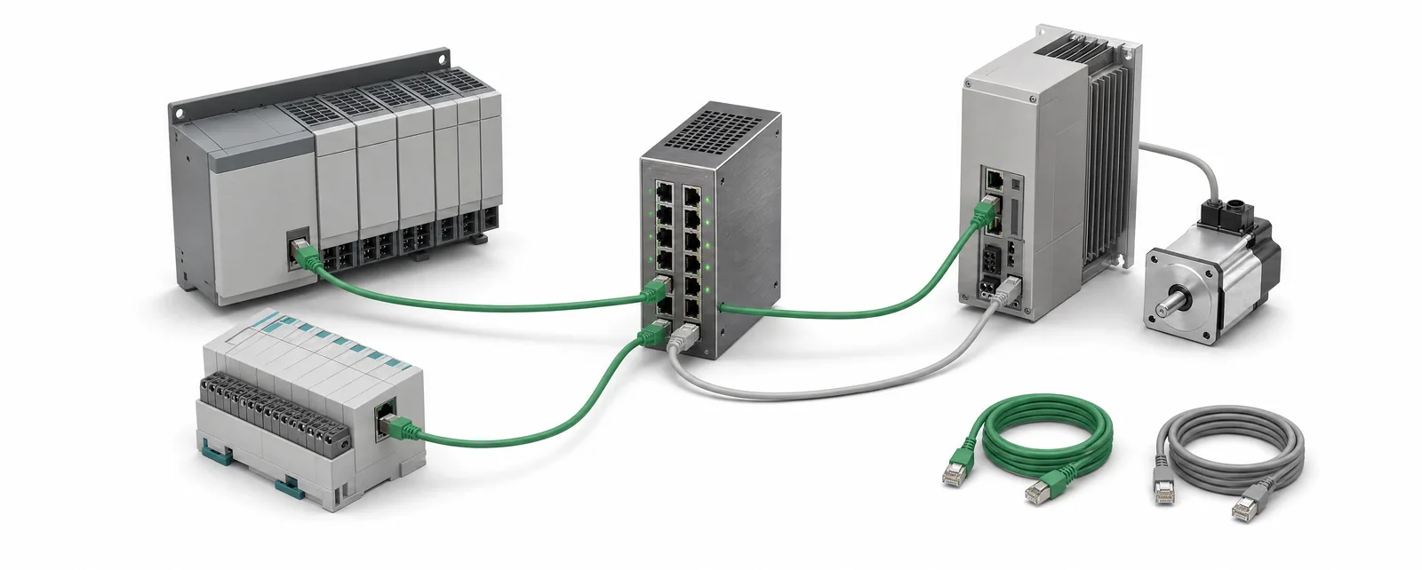
Conceptual equipment illustration.
Choose between PROFINET and EtherNet/IP by checking the controller, connected devices and functions your machine requires. Both are industrial Ethernet technologies. The useful comparison is whether the proposed combination supports the I/O, motion, diagnostics and maintenance work that the machine needs.
For an existing installation, a supported network with working spare parts and familiar engineering tools is a strong starting point. A change becomes worth evaluating when equipment replacement, an unavailable interface or a required new function creates a clear reason to move.
Start with the Equipment List
List the controller and every drive, robot, remote I/O station and inspection device that will connect to it. Record the exact product variant and firmware, not just the manufacturer’s name. Include communication option cards, runtime licences and the engineering software used to configure each device.
For each connection, identify the function: exchanging a few status signals, controlling a positioning axis, transferring inspection results or implementing a specified safety function. These have different integration requirements even when the connector looks the same.
Use this inventory alongside PLC migration planning. Keeping the controller but replacing a drive is a different project from replacing the controller and rebuilding the machine network.
Compare the Required Features
| Decision | PROFINET | EtherNet/IP | Evidence to request |
|---|---|---|---|
| Ordinary machine I/O | Controller and device support for the intended I/O exchange | Scanner and adapter support for the intended I/O connection | Exact device variants and configured process-data map |
| Coordinated motion | The required motion profile and timing capabilities, including IRT where specified | The required motion capabilities, including CIP Motion and synchronisation where specified | Compatibility across controller, drive and network design |
| Safety communication | Suitable safety devices and the specified PROFIsafe implementation | Suitable safety devices and the specified CIP Safety implementation | Supported safety configuration and validation scope |
| Device configuration | Compatible GSDML device description and engineering tool | Compatible device profile, EDS or platform-specific configuration | Matching device/firmware documentation and a tested project |
| Maintenance | Usable device diagnostics and a replacement procedure | Usable device diagnostics and a replacement procedure | A demonstrated fault-finding and restore workflow |
PI’s PROFINET technology description distinguishes real-time communication and application profiles. ODVA’s EtherNet/IP overview explains CIP and its related motion, synchronisation and safety services. Treat those as capabilities to check on the chosen equipment; the protocol name alone does not establish a complete compatible system.
Keep the network’s nominal link speed separate from the machine’s required response. Controller task timing, device update settings, network loading and application processing all belong in the performance review. Request a test of the actual function under the intended operating conditions.
What the Device Files Tell You
PROFINET uses XML-based GSDML descriptions to represent device identity, structure and communication features. PI describes their role in its GSDML specification overview. EtherNet/IP engineering can use Electronic Data Sheet files; ODVA provides EDS tooling through its developer resources.
Save the device files with the engineering project and record the versions used during commissioning. Also document the configured data layout, units and meaning of each signal. A correctly imported device still needs its process data to agree with the machine program.
For example, a drive’s ready status and a robot’s permission to receive a part describe different conditions. The program must use each signal for its intended purpose. Naming the interface clearly makes future fault-finding easier than relying on an address list alone.
When the Existing Equipment Uses Both Networks
Keep each machine’s internal control network intact where it already performs the required work. The inter-machine connection may only need a small, defined exchange: ready, request, occupied, complete and fault, with the exact set determined by the process.
A gateway can be evaluated for that exchange. Specify the data mapping, update behaviour and response to communication loss. Motion coordination, safety communication and device diagnostics require their own supported implementation; they are separate acceptance items from transferring ordinary I/O data.
If the requirement is collecting production information, our legacy machine connectivity guide covers that scope. It helps distinguish a data connection from a change to the machine’s operating controls. For a drive replacement, use the servo retrofit requirements to check the motor, feedback and mechanical duty as well as the network interface.
Three Tests to Include in the Handover
- Run the required operating sequence. Check the smallest and largest data exchanges, the agreed update behaviour and the application’s response during representative production. Include the diagnostics needed by maintenance.
- Introduce a defined communication fault. Record how it is detected, which machine state is entered and what authorises recovery. Reconnect using the agreed procedure and verify that a stale command cannot start the wrong sequence.
- Restore a replacement device. Demonstrate the configuration, naming or addressing, parameter download and function check using the documented spare-part procedure.
Keep the test record with the final network drawing, device list and controller backup. Those documents form part of a maintainable machine control retrofit, alongside the physical installation and program changes.
Connecting equipment on different platforms? Tell us which PLC, drive or robot models are involved. We can discuss the required signals and the integration options for your machine.