
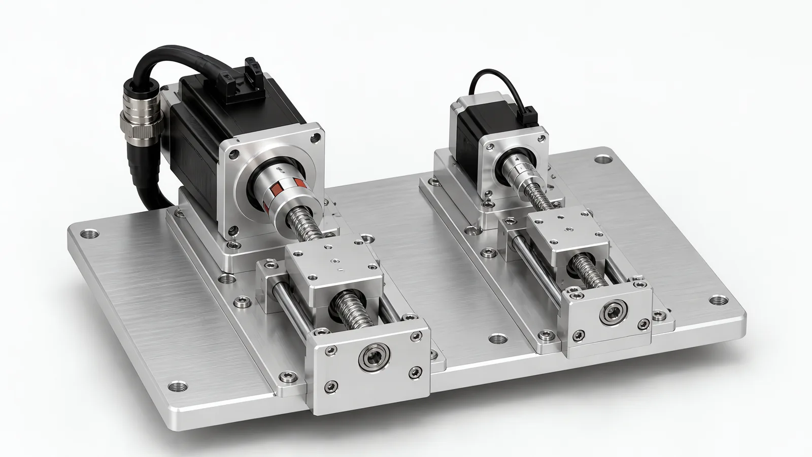
TL;DR: An open-loop stepper suits light, slower axes where a position error can be detected and recovered through the machine’s homing or checking sequence. A closed-loop stepper adds position feedback and drive-specific fault detection. A servo is a strong choice when the required torque at speed, acceleration or settling calls for it. Compare the motor-drive torque curve, feedback, duty and recovery method before comparing nominal resolution. For clamps, gates and ejectors that move between two fixed ends, check a pneumatic cylinder as well.
Motionwell designs custom production machines in Singapore using servo, stepper and pneumatic motion. This guide compares their load, control and maintenance requirements so a buyer can specify the axis behaviour before choosing the actuator. If the question started with repeated lost-position faults or long restarts, first use the machine downtime diagnostic method to separate an actuator limitation from feeding, sensing or recovery losses.
What Actually Separates a Servo Motor From a Stepper Motor?
Open loop versus closed loop
A hybrid stepper has many magnetic poles. The drive energises phases in sequence, the rotor snaps to each new magnetic position, and a standard 1.8-degree motor gives 200 full steps per revolution. In a conventional open-loop arrangement, the controller counts commanded pulses without measuring rotor position. A closed-loop stepper adds position feedback to the motor-drive system.
A servo system uses an encoder or other position sensor for feedback. In position control, the drive compares commanded and measured position and adjusts motor current to follow the motion profile. A jam can create a following error that triggers the configured drive alarm. The PLC and HMI then need to receive and handle that fault.
An open-loop stepper can lose position without reporting that position error. Closed-loop stepper and servo drives can report position-related faults. Connect the selected drive’s alarm and status signals to the PLC, and test the resulting stop and recovery sequence.
How each one makes torque
The stepper holds its rated torque at zero speed and loses it as speed climbs. Winding inductance limits how quickly current can build in each phase, and back-EMF grows with rotor speed, so there is less current available to make torque the faster you spin. Torque falls off steeply past a few hundred rpm, and a typical hybrid stepper has little usable torque left by the time it reaches 1,000 rpm. A higher drive bus voltage pushes the curve out but does not change its shape.
A servo motor holds roughly flat torque from zero to rated speed, then moves into a constant-power region above it. It will also deliver short bursts well above its continuous rating, around three times continuous is a common figure on datasheets, which is exactly what a fast index-and-settle profile needs, since acceleration torque is transient while heating is governed by the RMS torque across the whole cycle.
Why Do Stepper Motors Lose Steps, and What Happens Next?
Three causes cover almost every case in the field:
- Torque demand exceeds torque available at that speed. Someone sized the motor from the holding torque figure on the front page of the datasheet, skipping the torque-speed curve at the operating point.
- Acceleration is too aggressive. Load inertia demands more torque during ramp than during the constant-velocity phase. A profile that runs fine empty misses steps once a real payload is fitted.
- Resonance. A stepper and its load form a spring-mass system. In the low-speed region the oscillation can be violent enough to slip a pole. Microstepping and mechanical damping help; passing through the band quickly helps more.
On an open-loop axis without independent position checking, an undetected lost step leaves the reported commanded position different from the actual position. That mismatch can shift a dispensing path or a camera trigger and produce rejects without a position-error entry in the fault log.
A closed-loop stepper uses rotor feedback to detect position error and apply the drive’s configured correction or alarm response. Check which alarms and position values the selected drive exposes to the PLC. Feedback does not remove the need to size torque across the operating speed and duty.
Why Are Resolution, Accuracy and Repeatability Not the Same Thing?
This is where most specifications go wrong, because steppers look excellent on the spec that matters least.
Resolution is the smallest increment you can command. A 1.8-degree stepper at 1/16 microstepping gives 3,200 increments per revolution, which sounds better than it is. Torque follows the sine of the electrical angle error, so a single 1/16 microstep only commands about eleven percent of holding torque. Under friction the rotor may simply not move until several microsteps have accumulated. Microstepping buys smoothness and reduced resonance. It does not buy accuracy.
Accuracy is how close the axis gets to the true target. Stepper datasheets typically quote a non-cumulative step angle error of around ±5% of a full step, and at the machine level that error is usually dwarfed by ballscrew lead error, coupling wind-up, backlash and thermal growth. A 23-bit servo encoder resolves the shaft to a level no mechanical transmission can honour.
Repeatability is the spread when the axis returns to the same target. This is the number your quality engineer actually cares about, and it lives in the mechanics, preload, guide quality, homing method, thermal state, far more than in the motor. ISO 9283:1998 treats pose accuracy and pose repeatability as two separate measurements with their own test methods for industrial robots, and the distinction carries over to any servo axis: a supplier’s repeatability figure and a buyer’s accuracy requirement can both be true and still disagree, so ask which of the two a quoted number is.
The engineering conclusion: pick the motor for torque, dynamics and feedback. Then get your accuracy from the transmission, the homing strategy, and inline measurement. On the machines where dimensional truth matters, we verify with an external measurement. Our machine vision inspection guide covers that side. On a plate thickness measurement machine we built, the axis only positions the part and a separate displacement sensor judges it, for exactly this reason: an encoder count is a statement about the motor shaft, while the tolerance sits on the workpiece. Everything between the two, screw wear, coupling wind-up, a frame that warms through the shift, turns a passing axis into a failing part with nothing on the HMI to show it.
What Does Heat and Duty Cycle Do to the Decision?
Stepper heating depends on the drive’s running and standstill current settings. Drives with standstill-current reduction draw less current between moves; some closed-loop packages also offer load-dependent current control. Check heat generation at the required duty, especially inside a sealed enclosure, in a cleanroom with a limited airflow budget, or near a precision fixture or camera where thermal drift moves the datum.
A servo draws current in proportion to load. An unloaded servo at rest draws almost nothing. On a vertical axis holding against gravity it draws real current, which is why we specify a motor brake on vertical axes, so nobody pays for continuous holding current, and why that brake matters for safety when power drops.
For any axis running continuously, size on RMS torque across the full duty cycle, not on the peak of the move.
What Does Each Option Really Cost to Own?
Hardware cost is the part everyone compares, and it is the part that matters least over a machine’s life. Cost drivers worth putting in the spreadsheet:
| Cost driver | Stepper systems | Servo systems |
|---|---|---|
| Motor and drive hardware | Generally lower; closed-loop feedback adds cost | Compare the motor-drive package at the required power |
| Feedback cable and connector | None for conventional open loop; closed loop needs compatible feedback and wiring | Feedback cable, correct routing and shielding |
| Commissioning time | Current and motion-profile settings; closed loop also needs feedback and error-response settings | Gain tuning and motion-profile verification |
| Sizing margin | Reserve torque margin against the load and acceleration for both open- and closed-loop systems | Sized to duty, with peak torque available for ramps |
| Diagnostics | Open loop: driver protection alarms may be available, without rotor position checking. Closed loop: position alarms and data depend on the drive and interface | Position, torque and alarm data depend on the drive and interface |
| Spares strategy | Compatible motor and drive; parameter backup for configurable units | Drive plus motor plus parameter backup |
Two hidden costs decide it more often than the hardware price. The first is undetected scrap from step loss on an open-loop axis without separate position checks. The second is the value of the data. A servo’s torque signal can provide a process signature. On a multi-station rotary assembly machine, for example, we would put a load cell or a torque-monitored servo press on every insertion station, record the force-versus-position curve against the nest that carried the part, and reject any assembly whose curve leaves the band set during validation. The same curves, viewed across a shift, show a feeder wearing or a press tool loosening before either produces a reject. Our page on how we design multi-station rotary assembly machines covers where that press data sits in the station layout and the validation record. An open-loop motor command does not provide that process measurement; it needs a separate sensor and data-acquisition path.
One more cost that has nothing to do with the motor: plant standardisation. A servo axis from the drive family your plant already runs usually costs less to own than a cheaper unfamiliar one, because the spare drive is already on the shelf, your technicians have already been trained on it, and the parameter backup lives in a toolchain somebody can open. The saving on the purchase order gets spent the first time an odd drive fails on a night shift and nobody can restore its parameters. We build on whichever control platform is already your standard, and we ask which one you run before we start selecting drives.
When to Use a Servo Motor: Which Applications Call for Which Actuator?
| Application | What we specify | Reasoning |
|---|---|---|
| Rotary indexing table, multi-station assembly | Servo | High inertia, short index time, and the settle must be verified before the next station fires |
| High-rate pick and place, variable pitch | Servo (or a SCARA robot) | Path and settling time drive the cycle, and a SCARA buys a tuned multi-axis package instead of axes you have to tune and sync yourself |
| Piston dosing pump, filling head | Servo | Fill volume is a direct function of stroke position, and a tight tolerance needs per-head closed-loop calibration, never one setting applied across the machine |
| Long gantry or robot linear track | Servo with suitable position feedback | Absolute feedback can retain position information across power cycles; brakes or load-holding measures provide physical retention. Define reference checks and gantry synchronisation for restart |
| Press, insertion or crimp station | Servo | Force and position logged together as the process record |
| Fixed-speed conveyor or pump | Induction motor and VFD | No positioning requirement, so a general-purpose drive is the cheaper right answer and a servo only adds tuning and spares |
| Label unwind, screw feeder, low-duty adjust axis | Open-loop or closed-loop stepper | Light, moderate-speed duty; select feedback and homing to suit the required position checks |
| Clamp, gate, ejector, two-position stop | Pneumatic cylinder | Two ends, high force, no tuning |
One row in that table is worth reading against a machine that chose the other way. The filling and sealing machine we delivered doses through pneumatically actuated diaphragm dispensing valves, which makes the dose a function of valve open time and supply pressure. That choice buys a wetted path with very few moving parts to clean and validate, and it gives up the per-head stroke calibration a servo piston would have offered. Which way a dosing station should go is a product question before it is a motor question, and it is set out on the custom filling machines page and in the pharmaceutical filling case study.
Pneumatic vs Electric Actuator: When Does Air Beat Both Motors?
Pneumatics can be economical for end-to-end clamping, gates and transfer motions. Size the cylinder, guidance and cushioning for force, side load and impact, then select seals and materials for the cleaning environment. On a wet-duty station, route exhaust and protect valves and connections as part of the design. Standardising compatible cylinders, fittings and service kits also simplifies maintenance.
Four requirements change the comparison:
- You need intermediate positions. Standard cylinders have two, plus whatever you can achieve with mechanical stops. Beyond that you are into proportional valves or servo-pneumatics, and an electric rod actuator is usually simpler.
- You need controlled velocity. Flow restrictors are open-loop speed control. The setting drifts with temperature, supply pressure, seal wear and lubrication, so the profile you commissioned in January is not the one running in June.
- You need force accuracy or force data. Cylinder force is pressure times area, and your supply pressure moves during the shift. When a process genuinely needs constant force, it needs closed-loop control: our force-controlled robotic grinding cell holds 100 N through an active force head.
- You need position information between the end stops. End-position switches confirm those positions; intermediate measurement requires a suitable displacement sensor and control arrangement.
The full pneumatic cylinder vs electric actuator comparison covers these feedback options and the complete axis, including valves, guides and power-loss behaviour.
Include compressed-air demand in the operating-cost comparison. Measure the duty and leakage associated with a pneumatic circuit, then compare the delivered work and annual energy with an electric axis. A simple clamp and a continuously cycling transfer axis can justify different choices.
On most Motionwell machines all three appear on the same frame: servos on the axes that need a profile, a stepper or two where duty is light, air on the clamps, ejectors and gates. Mixing them is what sizing each actuator to its own job looks like on a drawing.
How Does This Play Out on Retrofit Projects?
Control-system modernisation is now the largest single stream of work we run: replacing worn mechanical cams, obsolete DC drives and unsupported controllers on legacy production machines with a current PLC, servo and VFD platform. On that work the motor is rarely the hard choice. The engineering goes into deciding which axes have to become servo to get the result the customer asked for and which can stay as they are, because every converted axis brings a drive, a cable route, a safety function and a commissioning day with it, and an axis converted for neatness is pure cost.
The pattern repeats. A machine built around mechanical cams and pneumatics gets a new product variant, and the cam is not adjustable. Replacing the cam with a servo and an electronic cam profile turns a machining job into a recipe change. That is usually the whole business case, ahead of any speed gain. The same job also adds safety circuits, interlocks and guarding to current standards, which is a separate conversation covered in our notes on cobot and machine safety standards.
If you are scoping a new machine, the motion architecture is settled during concept design, and changing it later is expensive. Our special purpose machine design guide explains where that decision sits in the project timeline.
What Do You Need to Get the Specification Right?
Bring these six numbers to a motion review and the servo-versus-stepper question usually answers itself in the meeting:
- Stroke or travel, and the move distance per cycle
- Move time and settle time you need, plus cycles per hour
- Moving mass, and whether the axis is horizontal or vertical
- Required repeatability at the tool point
- Duty cycle: percentage of time under load, and ambient conditions (cleanroom class, washdown, temperature)
- Your plant’s control platform standard, preferred spares and the position/error signals needed for recovery