
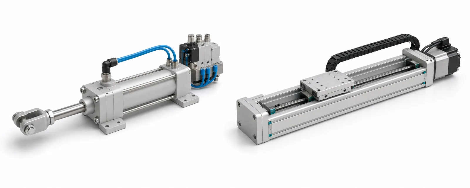
Conceptual equipment illustration.
Choose a pneumatic cylinder or an electric actuator by defining the movement first: where the load starts, where it stops, what force it needs and how long it holds position. A repeated end-to-end movement with an available air supply makes pneumatics worth evaluating. Several programmed positions, coordinated movement or a recorded pressing cycle make an electric axis worth evaluating.
The comparison is between two complete systems. A cylinder needs its valve, air preparation, tubing, sensors and mechanism. An electric axis needs its motor, drive, feedback, power supply and mechanical transmission. Compare both against the same duty before choosing parts.
Describe One Complete Cycle
Write the cycle in operating order. Include approach, contact, dwell, return and the wait for the next part. Then add the product variants and the position of the load during a loss of air or electrical power.
This description should identify the load mass, stroke, orientation, required speed and available space. For a pressing operation, also distinguish the force at the tool from the force produced by the actuator. The fixture, guides and transmission affect what reaches the workpiece; they belong in the mechanical design review.
A cylinder driving a guided slide and a bare cylinder pushing an unsupported load are different designs. Likewise, selecting a servo motor does not settle the stiffness, backlash or load capacity of the complete electric axis.
Compare the Function You Need
| Machine-axis requirement | Pneumatic system to evaluate | Electric system to evaluate |
|---|---|---|
| Repeated movement between two end positions | Cylinder with appropriate stops, cushioning and position detection | Point-to-point electric actuator with suitable end-position control |
| Several recipe positions | A positioning pneumatic system with the required feedback and control | Programmable axis with an appropriate motor, encoder and drive |
| Controlled contact or pressing | Pressure regulation plus the sensing needed at the process | Force-capable axis control and, where needed, force measurement at the tool |
| Long holding period | Holding method, pressure retention and leakage behaviour | Mechanical holding or brake arrangement, drive duty and heat |
| Coordinated axes | Controller and pneumatic architecture suited to the motion requirement | Motion controller, drives and communications supporting the required coordination |
Feedback belongs to the selected configuration. Festo’s linear motion technology guide describes sensor-equipped pneumatics, closed-loop servo pneumatics and both simple and more advanced electric positioning. The useful question is which configuration achieves the movement you need with a maintainable machine design.
If the decision favours an electric axis, our servo versus stepper comparison covers the next selection step. Keep the load and duty profile attached to that decision so the motor comparison remains relevant to the mechanism.
Four Workstations, Four Different Starting Points
A carton stop at a conveyor transfer. Evaluate the required stopping force, impact, cycle frequency and confirmation that the stop has retracted. A compact pneumatic arrangement may fit well when the air system already serves the station. Include the sensor and valve response in the release sequence.
A fixture that changes between product widths. Identify whether adjustment happens once per shift or on every cycle. A manually set stop, a simple powered adjustment and a continuously programmable axis solve different production needs. Select the level of automation that matches the changeover.
An assembly press with a process record. Define the force and displacement information required for acceptance. Ask how it will be measured, stored and associated with the part. Motor feedback or air pressure alone may not represent the complete interaction at the workpiece; specify the measurement arrangement with the process.
A lifting axis that pauses above a work area. Design the holding and controlled recovery behaviour before comparing purchase prices. Check the load path and the means of retaining the load through the relevant fault conditions. This applies to either energy source.
On a rotary indexing assembly machine, different stations can use different actuation. One station may need a short clamp movement while another needs a programmed insertion profile. The common requirement is that their actions fit the machine sequence and available cycle time.
Calculate Energy for the Same Work
For pneumatics, collect air consumption per cycle, cycle count, supply pressure and the compressed-air system’s energy cost. Include idle leakage and the method used to hold the load. For electric actuation, use the operating profile, drive losses, idle power and holding duty. A motor nameplate rating alone is not a measurement of energy used per finished part.
Compare a complete production period, including waiting time and changeovers. Keep the assumptions alongside the result so a different shift pattern can be evaluated without rebuilding the calculation. Initial equipment cost, engineering time, maintenance and energy should remain separate entries in the comparison.
Specify How the Axis Will Be Handed Over
Ask for the final settings, sensor positions, control sequence, replacement procedure and recovery instructions. A useful trial runs the smallest and largest variants, checks the required positions or process results, and demonstrates the agreed restart behaviour after a simulated fault.
This connects actuator selection to custom automation design: the axis, fixture and controls must work as a station, not simply as independently selected components.
Choosing an axis for a new or existing machine? Tell us what it needs to move, hold or press. We can discuss the motion sequence and how it fits the rest of the machine.