
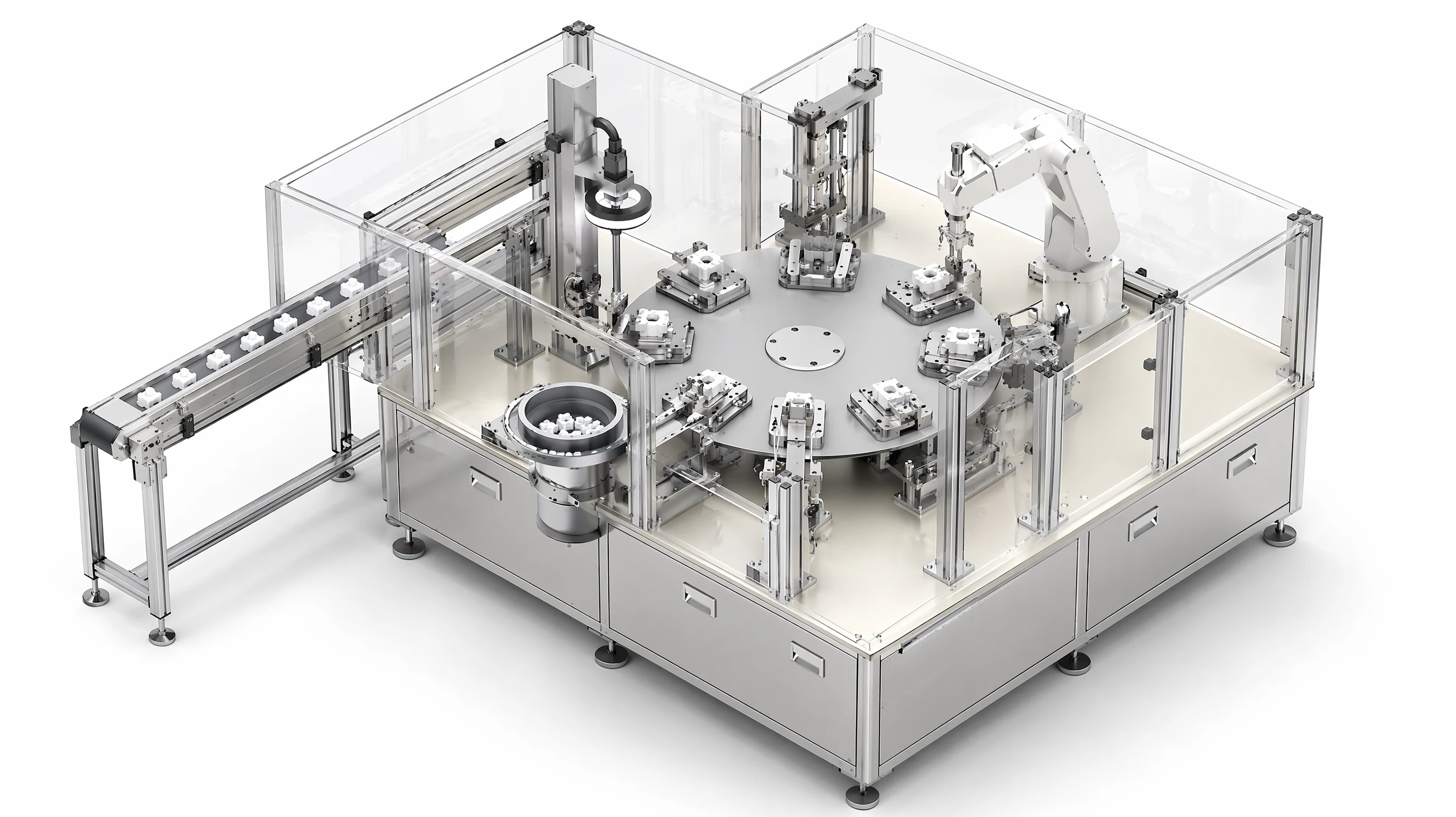
Motionwell designs multi-station rotary indexing assembly machines in Singapore. A cam-indexed or servo-indexed dial carries components through feeding, pressing, inspection and unloading within one guarded enclosure. The design starts with the operation times, part-location requirements and quality checks at each station.
Our SCARA panel assembly and three-head filling and sealing projects provide related experience in tooling, vision, dosing and machine controls. For a rotary layout, those disciplines are combined around the dial’s shared index-and-dwell cycle.
Whether a dial is the right architecture at all is a separate decision, worked through on our rotary indexing vs inline assembly page.
What Does a Rotary Indexing Assembly Machine Consist Of?
Seven things, and the order in which they are drawn matters more than the list.
The dial is a circular table with a nest at each division. The nest is cut around the part, locates it once at load and holds it through every station until unload, and that single-carrier property is what the architecture is bought for. The indexer rotates the dial by one division and holds it still during the dwell, and it is the component whose selection sets the machine’s rhythm, its position repeatability and how much of either is adjustable later. The tooling plate, a stationary plate above or around the dial, carries the stations, so a station acts on the part while both are held still relative to each other. The stations are the operations: load, press, dispense, screw, inspect, mark, unload, each with its own actuator, sensor and tooling. A dispense station carries its own set of decisions, set out on our dispensing and adhesive systems page. Feeders and escapements present components to the load stations from outside the ring. The guarding and safety system enclose the dial, its stations and the feeder outlets, with access points where an operator replenishes or clears a jam. The control system sequences the whole machine, holds the recipes and writes the records.
The drawing order that avoids the expensive mistake is dial diameter last. The diameter follows from the nest pitch, and the pitch has to clear the largest mechanism on the tooling plate, which is usually a press column or an inspection light head. Fix the stations and their mechanisms first, then the pitch, then the number of divisions, then the diameter. A dial sized from the part alone is redrawn when the first press station is designed.
The table below is the concept-stage checklist we run before anything is modelled.
| Element | Decided by | Locked when |
|---|---|---|
| Nest geometry | The part’s datum features and which surfaces may be touched | Part drawings approved |
| Station list and order | The process sequence, plus a verification after each operation that can fail | Process reviewed with the customer |
| Nest pitch | The widest station mechanism, with clearance for tooling removal | Station concepts drawn |
| Number of divisions | Station count plus any empty positions needed for access or settling | Pitch fixed |
| Dial diameter and indexer size | Pitch times divisions, and the inertia of the loaded dial | Divisions fixed |
| Indexer type | Dwell variation needed between stations, precision, cleanroom, cost | Cycle arithmetic done |
| Feeder positions | Which stations load components, and where the feeders can stand outside the ring | Layout drawn |
Which Indexing Mechanism Should Drive the Dial?
Four families, and the choice is made on how much the dwell needs to vary, how the part must be held still, and whether the mechanism can live in the room.
A mechanical cam indexer driven by a constant-speed motor converts continuous rotation into an index-and-dwell motion cut into the cam. The dwell ratio is fixed by the cam profile, the motion is smooth, the mechanism cannot lose position, and nothing has to be tuned. It suits a process whose station times are settled and similar.
A servo-driven cam indexer keeps the cam for its mechanical dwell and rigidity, while the servo controls the index timing and shared dwell duration. All stations on the same dial share that stop, so the longest operation still sets the required dwell. Motion profiles live in controlled recipes, with changes tested against station clearance, product handling and the agreed qualification scope.
A direct-drive rotary table removes the cam and the gearing: a torque motor and a high-resolution encoder drive the dial directly, so the division count is a software setting and the position is closed-loop. Rigidity during the dwell has to come from the motor holding torque or a separate lock, so a heavy press load on the table needs its own reaction path. The mechanism is quiet and free of cam lubricant, which is attractive inside a classified room.
A Geneva mechanism or pneumatic indexer is the low-cost end. The dwell is fixed, the motion has a hard acceleration profile that shakes small parts in their nests, and a pneumatic index cannot be sped up or slowed down per station. It is adequate for a small number of divisions and a forgiving part, and wrong for a precision dial.
| Mechanism | Shared dial dwell | Position held by | Adjust after build | Fits a cleanroom | Where it is the right choice |
|---|---|---|---|---|---|
| Mechanical cam indexer | Fixed ratio, same for every station | The cam, mechanically | New cam | With lubricant contained | Settled process, similar station times |
| Servo-driven cam indexer | Programmable shared dwell within the mechanism’s operating limits | The cam, with servo control of timing | Recipe change | With lubricant contained | Adjustable cycle timing with controlled motion recipes |
| Direct-drive table | Fully programmable | Motor holding torque or a separate lock | Recipe change, including division count | Well, no cam lubricant | Precision positioning, clean environments, light press loads |
| Geneva or pneumatic | Fixed | The mechanism | Not adjustable | Poorly, pneumatic exhaust | Few divisions, robust parts, low budget |
Two consequences follow whichever is chosen. The index repeatability of the dial is a property of the indexer, the dial bearing and the nest together, measured at the nest, never quoted from the indexer’s datasheet, and it should be stated as a measured figure at factory acceptance with the method alongside it. And the index move is dead time for every station on the table, so an indexer that moves faster earns its cost across the whole machine, which is why the dial’s inertia, and therefore its diameter and material, are part of the same decision.
How Are Stations Laid Out and the Dwell Balanced?
Write the process as a list of operations with the seconds each one needs beside it, before a station is drawn. On a dial there is one dwell, the longest operation sets it, and the cycle is that dwell plus the index move. That arithmetic is worked through on the comparison page linked above; here the question is what to do about it in the design.
Long operations can be moved to a parallel bank or an offline fixture, leaving the dial to handle shorter operations in a shared nest. Another option is to split a divisible process across stations, or duplicate a process so alternate parts use parallel capacity. Each arrangement needs a time chart showing how the work overlaps. A servo indexer adjusts the shared cycle profile; independent station timing requires a transfer or process arrangement that decouples the long operation from the dial.
Station order carries its own rules. A verification station follows every operation that can fail in a way the next operation would hide. Load stations sit where the feeders can stand outside the ring with a short, straight track in. The unload station sits where the reject path and the good path diverge without crossing the load side. Empty divisions are not wasted: one gives a technician a place to reach a nest without a mechanism above it, and one between a dispensing station and a press gives a bead time to settle. A process station needs a reaction path for its force into the frame; a verification station needs lighting space above the nest and a result tied to the nest position; an unload station needs two exits, good and reject, neither crossing a load side.
The reaction path deserves its own paragraph. A press station that reacts its force through the dial bends the dial and its bearing, and the deflection is repeated every cycle at every position. A press station should react its force through a C-frame or a column into the machine base, with the dial carrying only the part, and the nest stiff enough that the part does not move under load. That decision is made when the tooling plate is designed, and it is the reason the tooling plate is drawn before the dial.
Choose each station’s actuator from its motion requirement. A two-position clamp and a press that records force against travel need different control arrangements; our pneumatic and electric actuator selection guide compares those duties before cylinder or motor sizing.
How Is a Press Station Built So the Force Curve Means Something?
It means the force measurement goes in the load path, the displacement measurement goes on the tool, and the pass window comes from the part.
A press station on an assembly machine has three jobs: apply the insertion force, measure what happened, and decide. The measurement is a load cell in series with the tool, so the force read is the force reaching the part, plus a displacement sensor on the ram, so that force can be plotted against position. The pair produces a force-displacement curve, and it is the curve that carries the information. A component that is misaligned shows force rising too early; a missing component shows too little force at the expected position; a cracked or deformed component shows an irregular profile. Each of those is attributed to this station on this part, which is what a final inspection cannot do. Why a curve is better evidence than a flag, and what it is worth in a regulated plant, is set out on our medical device assembly machine page.
The actuator choice follows from the curve. A pneumatic press with a load cell gives force feedback and a stop-on-limit, with the force set by pressure. A servo press adds controlled velocity, a programmable stroke and a hold at position, so it can slow before contact and stop on force, on position or on a combination of the two. For a small, delicate insertion the servo press is the answer; for a robust press-fit on a metal part a pneumatic press with monitoring may be enough.
| Design item | The choice | Why it matters on a dial |
|---|---|---|
| Force measurement | Load cell in series with the tool | Reads the part |
| Displacement measurement | Sensor on the ram, referenced to the nest | Curve against position, so a short part and a misaligned part look different |
| Reaction path | C-frame or column to the base | Keeps the press load off the dial and the indexer |
| Nest under the press | Hardened or backed, with the part’s datum supported directly under the load | Nest deflection would appear on the curve as compliance |
| Window definition | Force limits at defined positions, taken from part trials | A window copied from a similar part rejects good parts or passes bad ones |
| Stop behaviour | Stop and flag on out-of-window during the stroke | Stops the press from finishing a bad insertion and damaging the mating part |
The window is the part of the design that cannot be done at a desk. It comes from pressing a sample set on the actual tooling, including deliberately faulty samples, and reading where good and bad separate. That trial belongs in the design programme with sample parts from the customer, and it is one reason the schedule wants real components early.
The press fit machine guide checks where force and displacement are measured and how fixture deflection enters the result. For other joining stations, compare heat staking and ultrasonic welding by joint function, then size the selected ultrasonic welding equipment around its tooling and process trial.
The dial also depends on its supply and changeover arrangements. A centrifugal feeder needs to follow the stop-start demand at the escapement. The flexible vs fixed automation guide explains how change parts and programmable stations can coexist with a dedicated index sequence.
Where Do Vision Gates Belong on the Table?
A gate belongs after every operation whose failure the next operation would hide, and nowhere else on the table.
A vision gate is a camera, a light and a decision, and each of the three has a space cost on a dial. The camera needs a working distance above the nest. The light, and a dome light in particular, needs volume directly over the station, which pushes the nest pitch out for every division on the table because the pitch is set by the widest mechanism. The decision needs a result tied to the nest position, so the controller knows which part failed once the dial has indexed on. Gates are placed sparingly for that reason: one after the components are loaded, to confirm presence and orientation before a press acts on them; one after the last forming operation, for the finished geometry; and one at unload where the sort is made.
Lighting is decided by the part. Translucent or polished parts throw specular highlights under directional light, and a highlight sitting on an edge reads as a dimensional deviation to a contour algorithm, which is why a dome or a diffuse source is chosen for those and a low-angle or backlight for a matte part with an edge to find. That practice, and how a camera is specified against the defect to be found, is set out on our machine vision inspection page.
Two design rules keep the gate trustworthy. The first is that the camera judges inside the machine, against a window held in the recipe, and the result is written against the part before the dial indexes, so a reject is a record with a cause. The second is that the reject action happens at the unload station, with the part carried there in its nest, because ejecting from a mid-table station means a mechanism reaching into the ring at a division the operator cannot see.
How Do Parts Get Into the Nest and Out of It?
They come in from outside the ring, through a feeder and an escapement, into a pick point, and they leave through a sorted unload. The feeder decides more of the machine’s reliability than the dial does.
A vibratory bowl feeder orients components on a track and delivers them in single file to an escapement, which separates one and holds it at a fixed pick point. From the pick point a pick-and-place unit, a small cartesian or a SCARA arm, transfers the component to the nest. The feeder stands outside the guarded ring so the operator replenishes it without opening a guard, and so a mechanism whose whole function is parts sliding on steel sits outside the classified envelope on a cleanroom build. The track from feeder to escapement is short and straight, and the escapement holds the component in the attitude the placement needs, because a placement that has to re-orient a component is a placement that fails.
The design questions for feeding are their own subject: which feeder family suits which part, why a bowl is tuned, how much faster than the dial the feeder must run and what happens when it jams. They are on our part feeding and presentation page. What the dial design has to settle is the interface: a part-present signal at the pick point, a starved signal that stops the dial from indexing an empty nest, and a defined reset that returns the machine to a known state after a jam without losing the record of which nests hold which parts.
Unload adds result-based sorting to the handling sequence. A SCARA or cartesian unit removes the part and places it in the assigned tray or chute using the result stored against the nest. The outfeed buffer and tray-change procedure are sized against the required sustained output. A robot reaching into the guarded ring brings robot-system safety requirements into the assessment alongside the machinery standards discussed below.
An indexing machine needs one correctly presented component during its transfer interval. step-feeder to dial transfer covers the feeder, buffer and receiving-nest trial.
What Makes a Rotary Indexing Machine Cleanroom Compatible?
Three things make it compatible: its materials, its particle sources and its motion, all decided at concept, because none of the three can be changed once the frame exists.
A dial is a machine with a large bearing, an indexer full of lubricant and a set of nests that rub on parts several times a minute, and it will be asked to run inside an ISO Class 7 or Class 8 room. The delivered machines we have built for that class of room, the tray-fed filling and sealing machine and the cleanroom automated test equipment series, are the source of the practice: stainless steel structure with product-contact surfaces finished to be wiped and to survive the cleaning chemistry, a sealed indexer with lubricant contained, and nests machined from engineering plastics in place of aluminium. On the test equipment the specimen nests are PA66 nylon and POM, chosen because a non-metallic nest does not shed conductive particles and because a surface resistivity above 10^12 ohm keeps the fixture from loading a sensitive device; the cost, stated in the same record, is that engineering plastics creep under clamping load, so the nests are consumables on a replacement interval.
Motion is the part specific to a dial. Every index accelerates and decelerates the whole table, and a hard profile throws particles from the nests and the part. A cam indexer’s smooth profile and a servo’s programmable one are both better than a pneumatic index for that reason. Air handling has to be considered against the dial: a downflow room wants the stations placed so nothing that sheds particles sits above a nest, which is why press columns are kept clean and light heads are sealed. The full set of decisions, including whether the classified zone is the room or the machine, is on our cleanroom automation equipment page.
How Is the Safety Chain Built From ISO 12100 to IEC 60204-1?
It is built in that order, and the order is itself the design method.
ISO 12100 comes first. The limits of the machine are determined, including every operating mode the dial will see: production, setup, teaching a pick-and-place, feeder replenishment, jam clearing at a station, nest changeover and cleaning. The hazards are identified against each, and a dial has a specific set: the index motion, which is fast and carries every nest at once; the press stations, which apply force at points around the ring; the pick-and-place and any robot at load or unload; the feeder tracks and escapements; and the inertia of a loaded dial, which continues to move after the drive is cut unless it is braked. Risk is estimated and reduced in the standard’s order, inherently safe design first, then safeguarding, then information for use. That is where the decision is made that a guard door needs an interlocked safety function at all.
ISO 13849-1 comes second and answers how good each safety function has to be. Every access point identified in the assessment becomes a safety function with a required performance level, decided from the severity of the injury, the frequency of exposure and the possibility of avoiding it. A feeder replenishment door opened several times a shift onto a dial whose index is faster than a hand can withdraw is a different function from a maintenance door opened rarely with the machine isolated, and they are not designed the same. The register of functions, their levels, the architecture chosen and the validation of each is the method set out on our machine safety and compliance page. Where a SCARA or six-axis robot loads or unloads the dial, ISO 10218-1 applies to the robot and its integration alongside the machinery standards.
IEC 60204-1 comes third and governs the electrical build the safety functions live in: the supply disconnect, protection against electric shock, the emergency stop category, conductor identification, enclosure and documentation. It is the standard the panel is built to for a machine going to the EU market, with NFPA 79 as its counterpart for a US-market machine, which is why the destination market is settled before panel design starts. How the panel itself is designed and built is on our control panel design and build page.
| Step | Standard | What it decides on a dial | What it produces |
|---|---|---|---|
| Risk assessment | ISO 12100 | Which hazards exist in each operating mode, and whether a safety function is needed for each | The risk assessment record and the list of required safety functions |
| Safety function design | ISO 13849-1 | The required performance level of each guard door, light curtain, enabling device and stop | The safety function register, architecture, calculation and validation plan |
| Robot at load or unload | ISO 10218-1 | Robot-specific requirements and the integrated cell | Robot safety configuration and its verification |
| Electrical build | IEC 60204-1 | Disconnect, shock protection, emergency stop category, conductor and enclosure requirements | Schematics, panel build record, verification tests |
One decision on a dial is worth making early. The index motion is the hazard behind every door, so the safe state on any door opening is the indexer stopped and held, and a dial with real inertia needs a brake or a lock in that stop path. The stop category for the press stations is decided separately, because a press mid-stroke on power loss may need to retract.
What Does a Medical Device Customer’s Quality System Ask of the Machine?
It asks for evidence, on every part, in a form it can put into its own system. A machine that produces that evidence is designed differently from one that does not.
A medical device manufacturer runs under ISO 13485, and the machine is not certified to it. What the manufacturer’s system needs from the machine is process validation, traceability, control of the measuring equipment inside the machine, and records, and each of those lands on the design. Process validation means the machine’s parameters are documented, held in a controlled recipe and reproducible, and that the qualification evidence shows the process runs inside its limits. Traceability means a part’s identity travels with its nest from load to unload, and every measurement made on it is written against that identity. Control of measuring equipment means the load cells, the displacement sensors and the cameras inside the machine are calibrated instruments with a schedule, which is a design decision about access and reference standards. Records mean the force curves, inspection results and recipe changes are kept somewhere the manufacturer can retrieve and defend.
Where the records are electronic, and they are, 21 CFR Part 11 applies to those a predicate rule already requires, which settles what the controller and HMI have to log, who is allowed to change a recipe and what audit trail follows. Access levels, time synchronisation, retention and the binding of a signature to a record then become design requirements on the control system, and they are cheaper built in than added.
The validation itself follows GAMP 5, which sets the software category of the machine’s control software and, from it, how much validation evidence the machine has to carry. Control software written by the machine builder for one machine sits in a higher category than configured standard software, and the second edition puts more weight on the service provider, which is us. The practical shape is a specification the machine is tested against, protocols for installation, operational and performance qualification, executed records and a summary report. How that is split between builder and customer, and where commissioning data can be reused for qualification, is on our computer system validation page.
| Quality system need | Where it lands on the machine | Design consequence |
|---|---|---|
| Process validation | Recipes, parameter windows, qualification protocols | Parameters are controlled values with owners |
| Traceability | Nest identity from load to unload, results written per part | Every result carries the nest position and the part identity |
| Measuring equipment control | Load cells, displacement sensors, cameras | Calibration access, reference standards, a schedule in the manual |
| Electronic records | Controller and HMI logging, audit trail, access levels | Part 11 requirements designed into the control system |
| Software validation | Control software category under GAMP 5 | Specification, test protocols, executed records, summary report |
The consequence for the mechanical design is the one that surprises buyers: a machine that is easy to adjust is a liability after qualification. Every hand-adjustable stop, every free-turning screw that sets a position, is a parameter without a record. Positions that matter are set by machined datums, shimmed and locked, or by a motorised axis under recipe control, and the adjustment that remains is the one the recipe can log.
When Should You Compare an Inline or Hybrid Layout?
Long process dwells can use parallel positions or an offline step linked to the dial’s part records. A wide variant mix may favour an inline or hybrid layout, while large parts call for particular attention to dial diameter and technician access. Our rotary indexing vs inline assembly page compares those arrangements.
Before fixing the division count, agree the station list and prove how the nest locates the part. An evolving process benefits from sample trials before the table geometry is released. Where a datum is difficult to hold, compare fixture features, vision correction and the required process tolerance together. A standard assembly machine can also be evaluated against the same sequence using our custom machine vs standard equipment guide.
What Do We Need From You to Start the Design?
We need the same things that decide the architecture, plus real sample components. Lead time on a machine of this kind runs 16 to 24 weeks from concept approval to factory acceptance testing on a standard build, and 24 to 32 weeks where cleanroom compatibility or full validation documentation applies. The design happens at Woodlands Link with an in-house design team of eight, so a Singapore buyer attends the factory acceptance test without flying to it. The regulated context for medical device work is on our medical device automation page.
Standards Used in Machine Design and Validation
These references inform the design, testing and documentation described on this page. Each row links to its primary source and records the edition checked.
| Standard | Current edition | What it means for your machine |
|---|---|---|
| ISO 12100: Safety of machinery, general principles for design, risk assessment and risk reduction | ISO 12100:2010 (a revision is in draft as ISO/DIS 12100) | The type-A standard every machine risk assessment starts from: hazard identification, risk estimation and the three-step reduction order of inherently safe design, safeguarding, then information for use. ISO 13849-1 answers how good a safety function has to be; ISO 12100 is where the decision that a safety function is needed at all gets made and documented.Checked 8 Sep 2026 against ISO catalogue page iso.org/standard/51528.html; ISO/DIS 12100 listed at iso.org/standard/88578.html |
| ISO 13849-1: Safety of machinery, safety-related parts of control systems | ISO 13849-1:2023 | Provides the design method for safety-related control functions, including architecture, component reliability, diagnostic coverage and common-cause failure measures. The machine risk assessment establishes the required Performance Level; design calculations and validation provide the evidence for each function.Checked 1 Sep 2026 against ISO 10218-1:2025 normative references |
| IEC 60204-1: Safety of machinery, electrical equipment of machines, Part 1: general requirements | IEC 60204-1:2016 (sixth edition) with Amendment 1:2021; the European edition is EN 60204-1:2018+A1:2025 | It governs the electrical build of a machine: supply disconnect, protection against electric shock, emergency stop categories, conductor identification, enclosure and documentation. It is the standard a control panel for an EU-market machine is built to, and the counterpart to NFPA 79 for a US-market machine, which is why the destination market has to be settled before panel design starts.Checked 12 Sep 2026 against IEC webstore publication 26037 (IEC 60204-1:2016, released 13 October 2016; A1:2021 listed as IEC 60204-1:2016+AMD1:2021); BSI catalogue BS EN 60204-1:2018+A1:2025 at knowledge.bsigroup.com/products/safety-of-machinery-electrical-equipment-of-machines-general-requirements-3 |
| ISO 13485: Medical devices, quality management systems, requirements for regulatory purposes | ISO 13485:2016 (third edition) | Sets quality management requirements for organisations involved in medical devices. Equipment specifications and handover records support the manufacturer's processes for validation, traceability, measurement control and record retention.Checked 8 Sep 2026 against ISO catalogue page iso.org/standard/59752.html (third edition, 2016, replaces ISO 13485:2003) |
| ISPE GAMP 5: a risk-based approach to compliant GxP computerised systems | Second Edition, published July 2022 | Guides the lifecycle assurance of GxP computerised systems. Intended use, process risk, patient safety, product quality and data integrity shape the verification effort; software category and supplier assessment help plan the supporting evidence.Checked 7 Sep 2026 against ISPE, GAMP 5 Guide 2nd Edition publication page (ispe.org/publications/guidance-documents/gamp-5-guide-2nd-edition), stated publication date July 2022 |
| 21 CFR Part 11: FDA rule on electronic records and electronic signatures | Current eCFR text; most recent amendment to the part dated 2 March 2023 | Applies to electronic records maintained under FDA predicate rules and to the electronic signatures within its scope. Identify those records during machine specification, then design access control, audit trails, retention, accurate copies and signature binding around their intended use.Checked 7 Sep 2026 against eCFR versioner API (ecfr.gov/api/versioner/v1/versions/title-21.json, part 11), latest section amendment_date 2023-03-02 |
Frequently Asked Questions
Should a rotary assembly machine use a cam indexer or a servo-driven table?
A cam indexer where the station times are settled and similar, a servo-driven one where they are not. A mechanical cam gives a fixed dwell ratio, smooth motion, a position that cannot be lost and nothing to tune, which is the right answer for a mature process. A servo drive on the cam, or a direct-drive table without one, turns the dwell into a programmed number so a long press or inspection can have the seconds it needs without a new cam. The price is a motion recipe that has to be version-controlled and re-qualified when it changes, which in a validated plant is a real cost. Decide it from the list of operation times, and never from a preference for one mechanism.
Can a rotary indexing machine run inside an ISO Class 7 or Class 8 cleanroom?
Yes, if it is designed for the room from concept. The three things that decide it are materials, particle sources and motion. Structure is stainless steel with surfaces finished for the cleaning chemistry, the indexer is sealed with its lubricant contained, and nests are engineering plastics, so they do not shed conductive particles. Feeders stay outside the classified envelope because a bowl is parts sliding on steel for a whole shift. The index profile is kept smooth, since a hard pneumatic index throws particles from the nests. Our delivered filling and sealing machine and cleanroom test equipment series are built for that class of room, and the same practice carries onto a dial.
What records should a rotary assembly machine keep for a medical device customer?
The ones the customer's quality system needs to release the device: a result per part per station, tied to the nest position and the part identity, plus the recipe in force when it was made and who changed it last. On a press station that is the force-displacement curve; on a vision station it is the measured values and the decision. Under 21 CFR Part 11 those records need an audit trail, controlled access to recipe changes and a retention scheme, and under GAMP 5 the control software that writes them carries validation evidence in proportion to its category. Designing the logging in at concept costs little; adding it to a commissioned machine means revalidation.