
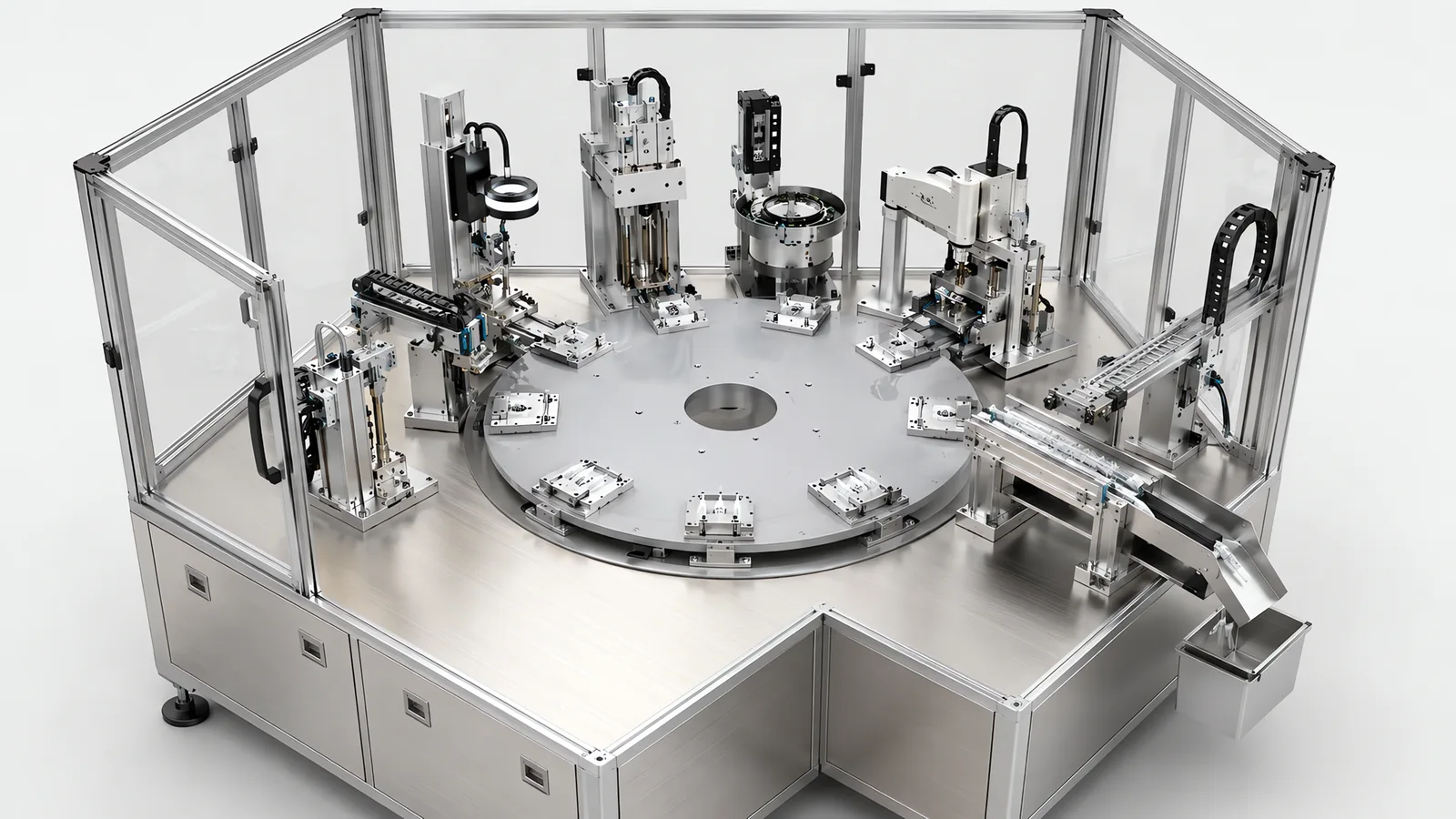
Motionwell Automation builds medical device assembly machines in Singapore, meaning multi-station machines that assemble a device and produce the evidence that it was assembled correctly. The design practice on this page is a cam-indexed or servo-indexed dial carrying a nest per division. Press stations monitor insertion force through the stroke and log every press against the part identity, so an out-of-band assembly is rejected at the station that caused it. Vision stations record measured values and images against the same identity. Product-contact surfaces and nests are chosen against the cleaning chemistry and the cleanroom class, and the whole build is wrapped in a qualification package structured under GAMP 5, with installation, operational and performance qualification protocols executed alongside the customer’s quality unit.
The delivered work that practice draws on is on this site: a vision-guided SCARA sensor panel assembly line that logs fastener torque against every panel serial number, and a tray-fed filling and sealing machine installed in a pharmaceutical customer’s cleanroom, a class of machine we can supply with IQ/OQ/PQ protocols. Machines are designed, assembled and tested at our Woodlands Link facility, and the company has delivered more than 150 special purpose machines since 2014 under ISO 9001:2015 and bizSAFE Level 3.
We prepare the machine instrumentation, records and qualification protocols with your quality team, so each critical assembly requirement has a defined test and approval route.
The industry context sits on our medical device automation page, and the dial architecture itself, indexer selection, station balance and the safety chain included, is worked through on our page on how we design multi-station rotary assembly machines.
What Makes a Medical Assembly Machine Different From a General One?
On a general assembly machine the deliverable is the assembled part. Here the deliverable is the assembled part and the record of how it was made, and the record is part of the product in a practical sense: a unit you cannot evidence is a unit you cannot release. Everything else on this page follows from that one sentence.
The design consequence is that the unit of engineering stops being the operation and becomes the operation plus the evidence it produces. Every station that can affect the device needs three things a general station does not carry: an instrument measuring what the station changes, a window the measurement is judged against inside the machine, and a log tying the result to the unit. A transfer or an empty index position needs none of that, and instrumenting it buys data nobody will read.
Which stations fall on which side of that line is settled at concept stage, because it sets the control architecture for the whole machine. Three things follow that reshape the machine. Verification moves upstream, from a final inspection that tells you a unit is bad to a station measurement that tells you which operation made it bad. The reject path becomes a record. And every parameter that can affect the device acquires an owner and a permission. Each is taken up below.
Medical automation equipment is bought against that list, which is why two machines with the same throughput are not the same machine. The design-area comparison with a general industrial build is set out in our note on medical device assembly automation.
Why Does the Precision Core Usually Go on a Dial?
Two reasons that are specific to regulated device assembly, and one counterweight that overrides both.
The first is registration. On a rotary table the part is loaded into a nest and stays in it until the last station releases it, so the orientation established at load is the orientation every later station works from. That is what makes an index repeatability figure and a nest tolerance meaningful together: the first is only worth having if nothing between the first station and the last is allowed to disturb what it positioned.
The second is that classified air is expensive floor. Twelve operations in a circle need a smaller clean envelope than the same twelve in a corridor, and a machine can carry that envelope itself: our cleanroom automated test equipment holds ISO Class 7 and 8 over its fixtures with 4 to 6 fan filter units sealed into the enclosure ceiling, standing in a normal factory bay. Station density therefore buys classified volume as well as rent, and a compact guarded perimeter around one table, with no access point every few metres.
The counterweight is that a dial’s station count is geometry, fixed the day the table diameter and nest pitch are drawn. Device processes acquire stations: a corrective action adds an inspection, a customer audit adds a check, a market adds a unique device identifier and the mark and its verification arrive as two more positions. If your sequence is not finished, the architecture argument goes the other way, and the full comparison, hybrid included, is on our rotary indexing versus inline assembly page.
What Does a Force-Displacement Curve Tell You That a Pass or Fail Cannot?
Of everything a medical assembly machine records, this is the one we would keep if we could keep only one, and it is worth being precise about why.
On a multi-station assembly machine we would build each insertion station as a press-fit actuator, pneumatic or servo, carrying a strain-gauge load cell in the press axis and a displacement sensor across the stroke, so insertion force is measured in real time through the whole press stroke. The PLC records the complete force-displacement curve for every assembly cycle. The control is closed-loop against a window: if the measured force leaves the programmed tolerance band at any point during the stroke, the press halts, the part is flagged for rejection, and the curve is logged against the part identity.
A press fit is an interference joint, and the joint is invisible once it is made: a correctly seated component and one that stopped a fraction short both present as an assembled device. The usual alternative is a test that pulls the joint apart, which destroys the unit and therefore samples. Recording force against displacement converts a destructively sampled attribute into a record held for every unit, and that is the whole argument.
| What the curve does | What it reads as | Status |
|---|---|---|
| Force above the window at any point in the stroke | Component misaligned | Rejection condition in the force window |
| Force below the window through the stroke | Component missing or undersized | Rejection condition in the force window |
| Irregular profile, though in band at the ends | Damaged part | Rejection condition in the force window |
| Target force reached short of the expected final position | The joint found resistance before it reached the seat | What the displacement axis adds to the same window |
| Final position reached with force low through the run-in | An interference fit that is not interfering | What the displacement axis adds to the same window |
The last two rows are why the record is force against position. Force alone can be right for the wrong reason; force plotted against displacement is a corridor in two dimensions, and a joint that arrives at the correct force in the wrong place falls outside it.
Three further returns come from the same data at different times. Immediately, it localises the fault, because the station that made the joint is the station that rejects it. Over a shift, it trends: a population sliding towards the edge of the window shows as movement in the curve well before it shows as a reject, which is how a moulding tool wearing at a component supplier reaches you as a chart. At audit, it is attributable, because each curve carries a serial number.
State the limit as clearly as the benefit. The curve proves the press. It says a component entered with the expected resistance and stopped in the expected place, and nothing about whether the finished device functions, seals or holds pressure; those are separate stations with their own instruments, on our automated test equipment and machine vision inspection pages. One consequence to settle early: a full curve per press, per cycle, per serial number is a meaningful data volume over a production year, as covered on the electronic device history record page.
The press fit machine selection guide connects the curve to frame stiffness, ram measurement and the finished joint. Where the assembly uses another joining method, compare heat staking and ultrasonic welding against retention or fusion requirements; the ultrasonic welding equipment guide then covers tooling and cycle-record decisions.
Small adhesive deposits need a defined quantity and placement window. jet-deposit qualification describes the fluid and motion trial without treating a valve as product qualification.
Where Do the Particles Actually Come From on an Assembly Machine?
Assembly machines have a harder version of the cleanroom problem than conveying or packing equipment, because their particle sources sit where the product is. Four are specific enough to this class of machine to name.
The first is pneumatic exhaust at the press. A standard cylinder vents through a muffler on every stroke, releasing air into the room at the precise moment the tooling is over the device. The answer is a cleanroom-rated cylinder with its exhaust piped back to a manifold outside the clean zone, and the reason to settle it at concept is that the later fix is not a parts swap: routing exhaust off the table after the fact means new penetrations through an enclosure that has already been qualified, and requalification of the space around it.
The second is the bowl feeder. A vibratory feeder is a mechanism whose entire function is components sliding against a steel track for a whole shift. On a rotary machine we place the feeders outside the ring, orienting and presenting components to a pick point at the load station, so the particle-generating mechanism sits off the table even though the loading position is a station on it. That separation is decided at concept, and there is no later fix for it either.
The third is the nests themselves. Every load and unload is a rubbing contact against the part, repeated for the life of the tooling, which is why nest material is selected for wear as much as for location, and why nests are planned as consumables.
The fourth is everything that moves under the product plane. Guides, screws, belts and cable carriers behave here as on any cleanroom machine, and the treatments are the same ones worked through in our cleanroom automation guide.
The design move underneath all four is a boundary: the generating mechanism on one side, the product plane on the other, filtered downflow between them, and every crossing sealed.
How Do Material Choice and Cleaning Chemistry Decide Each Other?
An easy gap to leave in a specification is to name a steel grade for the frame and say nothing about the surfaces that touch the device. On an assembly machine much of the product-contact area is not steel at all: it is nests, gripper pads, press tooling faces and the chute the finished unit slides down, and those are the surfaces a cleaning validation has to cover.
| Zone | What our medical builds specify | What decides it |
|---|---|---|
| Product-contact surfaces on a device assembly machine | Stainless steel, with the alloy grade and the surface finish both named in the specification | The cleaning agent, and whether the surface touches the device |
| A fluid path, where the same line also fills | The same specified alloy and finish as the row above, with the dispensing valve and its diaphragm selected against the liquid, as on our tray-fed filling and sealing machine | Contact with the product liquid, and the cleaning method |
| Nests and locating fixtures | POM and nylon, contact surfaces machined and polished to the location tolerance the process needs | Location, wear, insulation, with no marking of the device |
| Grippers, press faces and chutes | Selected against the surface they touch | Marking risk and the cleaning method, covered on our end of arm tooling page |
| Enclosure, seals and labels | Wipe-down geometry, gaskets chosen against the disinfectant, markings etched | The cleaning procedure |
The choice between SUS304 and SUS316 is usually driven by the cleaning chemistry, chlorides in particular. Engineering plastics are chosen for different reasons: POM holds dimension at a friction coefficient of 0.2 to 0.35 against steel, and neither POM nor nylon sheds conductive debris into a Class 7 or 8 room the way a metal nest can, or brings a static discharge path to sub-components that do not tolerate one.
Two consequences follow that a specification can easily leave out. Polymer nests creep under sustained clamping load, so they are wear parts with a planned replacement interval, and that interval belongs in the maintenance schedule at handover, long before a dimension drifts. And the nest has to survive your disinfectant as well as your part: one that swells or crazes in service has lost its tolerance, and tolerance was the reason it existed. Send the cleaning agent and the contact time with the drawing.
How Does a Unit Stay Identified From Component to Finished Device?
The machine is where lot-level component identity is bound to unit-level device identity, and it cannot bind more than it knows.
Upstream, a bowl feeder destroys individual component identity by design. Components are traceable to the load that went into the hopper and the changeover event that ended it. The record should say so, because a traceability claim implying piece-level component identity through a vibratory feeder will not survive an auditor asking how.
Downstream of the load station a dial makes unit identity almost free: the nest position is the part identity for the whole build, so every station’s result is attributable without reading anything off the part. That is what lets a dial store a force-displacement curve at each press station against a serial number, link the vision results, measured values and images to the same one, and sort by inspection result at the output.
So the split to write into the specification is short. Bound at unit level: force and displacement at each press, the vision measurement and its image, the station sequence with timestamps, and the reject reason. Held at lot level: component lots by feeder load, nest sets by change part record, and cleaning, environmental and maintenance events against the machine.
Two things then decide whether that record is usable. Rejects have to be reconciled, so what the machine says it made, what it passed and what it removed agree; that discipline is on our code reading and traceability page. And the record has to land somewhere controlled. We deliver that side as its own scope: an electronic device history record system taken as a standalone order and accepted in August 2026, rolling out site by site for a medical device manufacturer.
What Evidence Does Each Qualification Stage Want From the Machine?
Three stages, three questions, and on an assembly machine they land on different hardware. What follows is what the machine has to hand over, and not how the protocols are structured; the V-model, GAMP categorisation and traceability matrix are on the computer system validation page.
| Stage | The question it answers | What an assembly machine has to produce |
|---|---|---|
| Installation qualification | Is this the right machine, correctly installed? | As-built drawings and schematics; components verified against the BOM; calibration certificates traceable to national standards for every load cell, displacement sensor and instrument that judges a device; material certificates and surface finish records for product-contact parts and nests; firmware and program versions for PLC, HMI, drives and vision, with an archive; utilities verified, compressed air quality included |
| Operational qualification | Does it do what the specification says, at the limits? | Every sequence step and alarm exercised with faults created deliberately; the force window proven by presenting a missing and a misaligned component and showing the station halts, rejects and logs; index repeatability; access levels, so an operator cannot change a qualified parameter; audit trail content and its resistance to alteration; power removed mid-press and a defined recovery with the record intact |
| Performance qualification | Does it keep doing it with your product, people and procedures? | Real components, production operators and approved SOPs across runs and sample sizes defined in the approved protocol; cleanroom builds include the agreed environmental tests for airflow, recovery and particle counts |
The operational qualification row is where this class of machine differs most. A filling machine is challenged by dosing at the ends of its declared range; a press station is challenged by presenting it with the defects it exists to catch, which means somebody has to make bad parts on purpose and keep them labelled. Agree who prepares those challenge samples early, because a protocol calling for a misaligned component and a stores cupboard containing none is an easy way to lose a week at site acceptance.
Protocols are prepared under GAMP 5, and on our GMP builds the commissioning and qualification sequence follows ISPE Baseline Guide Vol. 5, which matters commercially: engineering commissioning runs first and generates test data, then qualification uses that data where it was collected under controlled, documented conditions. Factory acceptance testing happens at Woodlands Link before shipment and site acceptance testing at your cleanroom, and the package includes protocols, executed test records, deviation reports and a validation summary report. Where force curves and inspection results have to be retained as records, 21 CFR Part 11 decides where they are stored, who may alter them and what audit trail follows.
Why Is a Machine That Is Easy to Modify a Liability After Qualification?
Because adjustability and evidence pull in opposite directions, and the second half of that trade is easy to miss when the machine is being bought.
On a general industrial machine, a technician turning a knob, nudging a stop or retuning a setpoint from the HMI is a feature, and a good machine has plenty of them. After performance qualification every one of those is either a controlled parameter, with permissions, an audit trail entry and a change control behind it, or an uncontrolled one, in which case the record no longer describes the machine that made the product. There is no third category, and an audit trail showing a press force changed overnight with no impact assessment attached is worse evidence than no adjustability at all.
The design goal is therefore not a machine without adjustment. It is a machine where everything that can affect the device is a controlled parameter with a bounded re-test, and everything else is fixed in metal.
| Adjustable feature | Why you want it | What it costs after qualification | How the design bounds it |
|---|---|---|---|
| Press force and window setpoints | Tuning during ramp-up and after a component change | A qualified process parameter changed, so an impact assessment and re-testing of that station | Recipe-controlled, permission-restricted, one audit trail entry per change |
| Motion profile per station on a servo indexer | Each station keeps the dwell it needs | A recipe layer version-controlled and re-qualified when it changes, which is the trade-off a servo indexer carries into a validated plant | Profiles versioned in the software inventory, with change scope stated per station |
| Hand-set mechanical stops and slides | Fast setup on the floor | A setting nobody can prove was correct on the day | Keyed or dowelled positions, so a format change is a part swap with a record |
| Nest and change part sets for a new variant | One machine covers a device family | A change control with re-qualification of everything it touches | Agree the variant range before nests are cut |
| Vision thresholds and recipes | A new defect class appears | Changing what makes the decision reopens that decision’s qualification | Rule-based tools where the defect can be described, as on our surface defect inspection page |
One design principle keeps the cost of all this down, and it belongs in concept review: keep parameters local. A machine whose settings belong to individual stations, with no tuning constant shared between them, has a re-test scope of one station when something changes. A machine with a global adjustment several stations read has a re-test scope of the whole machine, a difference invisible on a datasheet and expensive for a decade.
So the question to put to your quality unit before detail design is which parameters they intend to treat as qualified.
When Is a Custom Medical Assembly Machine the Wrong Buy?
The device design is not frozen. Tooling is cut around a geometry. If the geometry moves after detail engineering starts, the nests, feeders and press tooling move with it, and that is scrapped work. Freeze the product first, or buy the inspection station now and the assembly machine next year.
The volume does not justify hard tooling. Where a variant will not run long enough to pay for nests and feeders across every station, a validated manual process with a good fixture and a trained operator is the better buy, and a shorter route to a qualified product.
The bottleneck is inspection. Inline verification usually pays back faster, disturbs a validated process less, and produces the defect data needed to specify an assembly machine correctly. If you cannot yet state your escape rate to one decimal place, automate the measurement first.
One operation takes minutes while the others take seconds. A cure, a soak or a functional test running for minutes does not belong inside a machine whose parts all move together. It goes offline, or into a parallel bank alongside the machine, whichever architecture the rest of the line takes.
You need one machine across unrelated device families. A dozen stations tuned to one device geometry are not re-taskable to a different device by recipe alone. New nests, new feeders and re-qualification add up to a rebuild presented as a changeover.
A proven standard machine already covers your assembly. Where a catalogue machine meets the specification at a lower price, the custom build has to be justified by something that machine cannot do.
Guarding scope follows from a risk assessment whichever way the decision goes. On a multi-station rotary machine the access point that assessment spends longest on is usually the feeder replenishment door, because it is the guard opened during production onto a dial whose index is faster than a hand can withdraw, and the required performance level assigned to it under ISO 13849-1 is worked through on our machine safety and compliance page.
What Has to Be Settled Before Design Freeze?
These are the decisions that cannot be revisited cheaply once the frame is welded and the nests are cut. Run them in order; the first that has no answer is where your concept review should start.
- The assembly sequence, operation by operation, with the seconds each one needs. Station count, architecture and cycle all follow from this list, and nothing useful is decided before it exists.
- Which stations can affect the device. That set decides where instruments go, and it is the difference between a machine you can qualify and one you can only inspect.
- The window for every measured operation, and who owns it. A press force and displacement band is a product specification: it comes from your process development, and we build the station to hold it.
- Cleanroom class, cleaning agents and contact time. Class drives the enclosure and the airflow; the chemistry drives the gaskets, the labels and the nest material.
- How components arrive, and whether component identity has to survive. Feeder, tray or magazine is a concept-stage layout decision, and it fixes how far upstream traceability can actually reach.
- The reject path and its reconciliation: where rejected units go, who counts them, and how the count is closed against production.
- Which parameters your quality unit will treat as qualified, and the variant range the nests must cover. The first sets the permission model, the recipe structure and the audit trail before the first line of PLC code; the second is cut into steel.
- The qualification split: who writes, who executes and who signs IQ, OQ and PQ, agreed at kickoff.
| Your situation | Start from | Why |
|---|---|---|
| Settled sequence, one device family, high volume, tight classified floor | Rotary dial with instrumented stations | Registration is established once and station density buys clean envelope |
| Sequence still moving, or a station likely to be added after launch | Inline, or a dial sized only around the finished core | Station count on a dial is geometry |
| Interference fits or press joints anywhere in the build | Force and displacement monitored at each press, logged per unit | The joint is invisible afterwards and the alternative test is destructive |
| Escape rate unknown, manual assembly still working | An inline verification station first | It produces the data that specifies the assembly machine |
| Device geometry not frozen, or several unrelated families on one budget | Nothing tooled yet | Nests and feeders are cut around one geometry, and re-tasking across families is a rebuild plus re-qualification |
| Existing qualified machine, only the record is missing | Bolt-on measurement scoped as a change control | Sensors, software and record retention all carry cost |
Standards Used in Machine Design and Validation
These references inform the design, testing and documentation described on this page. Each row links to its primary source and records the edition checked.
| Standard | Current edition | What it means for your machine |
|---|---|---|
| ISPE GAMP 5: a risk-based approach to compliant GxP computerised systems | Second Edition, published July 2022 | Guides the lifecycle assurance of GxP computerised systems. Intended use, process risk, patient safety, product quality and data integrity shape the verification effort; software category and supplier assessment help plan the supporting evidence.Checked 7 Sep 2026 against ISPE, GAMP 5 Guide 2nd Edition publication page (ispe.org/publications/guidance-documents/gamp-5-guide-2nd-edition), stated publication date July 2022 |
| 21 CFR Part 11: FDA rule on electronic records and electronic signatures | Current eCFR text; most recent amendment to the part dated 2 March 2023 | Applies to electronic records maintained under FDA predicate rules and to the electronic signatures within its scope. Identify those records during machine specification, then design access control, audit trails, retention, accurate copies and signature binding around their intended use.Checked 7 Sep 2026 against eCFR versioner API (ecfr.gov/api/versioner/v1/versions/title-21.json, part 11), latest section amendment_date 2023-03-02 |
| ISO 13849-1: Safety of machinery, safety-related parts of control systems | ISO 13849-1:2023 | Provides the design method for safety-related control functions, including architecture, component reliability, diagnostic coverage and common-cause failure measures. The machine risk assessment establishes the required Performance Level; design calculations and validation provide the evidence for each function.Checked 1 Sep 2026 against ISO 10218-1:2025 normative references |
Frequently Asked Questions
Why is a force-displacement curve better evidence than a pass or fail flag?
Because a flag records the machine's conclusion and a curve records what happened. A press fit is an interference joint, and once it is made a correct one and a marginal one look identical from outside; the other way to tell them apart is a pull test, which destroys the unit and therefore only ever samples. Recording force against displacement for every press turns that sampled attribute into a per-unit record.
How long does a validated medical assembly machine take to build?
Lead time runs 16 to 24 weeks from concept approval to factory acceptance testing on a standard build, and 24 to 32 weeks where cleanroom compatibility or a full validation documentation package applies. The qualification scope itself typically adds four to eight weeks, and that time is protocol writing, execution and review, so it runs partly in parallel with the build if the protocols are started early.
Can force monitoring be added to an assembly machine we already run?
Mechanically it is usually straightforward, since a load cell in the press axis and a displacement sensor across the stroke are bought parts. The control system and the record carry their own cost. The measurement has to be sampled fast enough through the stroke to be a curve, the window has to be judged in the machine and act on the press, and the result has to reach somewhere it can be retained and reviewed. On a qualified machine the change is also a change control with an impact assessment and re-testing attached, which is a legitimate cost and a surprising one after the purchase order.