
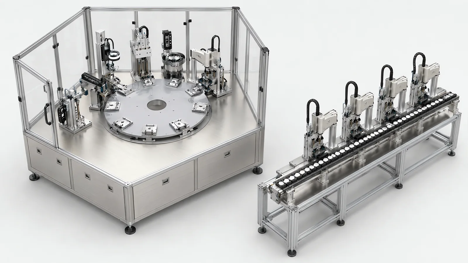
Motionwell Automation builds both architectures in Singapore, and the rotary indexing vs inline assembly decision is settled by process maturity and station count before it is settled by cycle time. The rotary side, from indexer selection through station balance to force-monitored press stations and the safety chain, is set out as a design guide on our page on how we design multi-station rotary assembly machines. The delivered inline reference is a vision-guided SCARA sensor panel assembly line where the stations sit in sequence, more than 15 panel variants share the line, and the camera measures each panel’s actual offset and corrects the robot before it places. Where this page cites delivered work on the rotary side of the comparison, it is the cleanroom test equipment series, a circular pallet transfer with stations arranged around the loop and a single load and unload position.
Machines are designed, assembled and tested at our Woodlands Link facility, and the company has delivered more than 150 special purpose machines since 2014 under ISO 9001:2015 and bizSAFE Level 3.
A dial is designed around one product family, and twelve stations tuned to one part geometry are not re-taskable to an unrelated device by recipe alone. What that architecture demands of a regulated build is on our medical device assembly machines page.
How a machine of either shape is scoped from concept to commissioning is in our guide to special purpose machine design. The robot inside either architecture is a separate decision, worked through on our comparison of collaborative and industrial arms.
How Does Each Architecture Actually Move the Part?
Assembly machine architecture is settled once, at concept stage, and everything downstream inherits it, so it is worth being precise about what is being chosen. Both machines hold a part still while an operation happens to it, then move it to the next operation. What differs is whether the parts move together or independently, and almost every trade on this page follows from that one difference.
A rotary dial holds parts in nests around a circular table. The table indexes one division at a time, every station acts during the same dwell, and the part stays in the nest it was loaded into until the last station releases it. Twelve stations means twelve parts on the table at once, each one division further through the build than the part behind it.
An inline machine puts stations in a straight sequence, and the part travels between them either directly or on a pallet. Each station controls when it releases, so the space between two stations can hold parts. That space is the whole difference: it is a buffer, and a buffer is what lets one station run slowly, or briefly not at all, without its neighbour going idle.
| Property | Rotary indexing dial | Inline sequence |
|---|---|---|
| How the part moves | All parts index together, one division per cycle | Each part advances when the next station is free |
| What sets the cycle | The dwell every station shares, plus the index move | The slowest station, softened by whatever buffer sits before it |
| Station count | Fixed when the table and nest pitch are drawn | Extended by adding a station and re-timing the sequence |
| Growth direction | The table diameter, so growth is expensive in every direction at once | One direction, along the line |
| Registration | One nest from first station to last, so orientation is established once | Re-established at each station, or carried by a pallet |
| Effect of one station stopping | The whole machine stops | Stations upstream and downstream run on until their buffers fill or empty |
| Where the operator stands | Outside the ring, at a fixed angular position per station | Beside the station that needs attention |
| Guarded perimeter | Compact, around one table | Longer, following the line, with more access points |
One caution before that table is used as a scorecard. The rows are properties of the architectures, and a specific build can soften almost any of them with money.
Why Does a Dial’s Cycle Belong to Its Slowest Station?
Everything on the table moves at once, so there is only one dwell to allocate. The cycle is that dwell plus the index move, and the dwell has to be at least as long as the longest operation needs. An inspection that wants a few seconds and a press that wants twice as long both act inside the same dwell window, so the shorter operation is allocated the longer number.
So the arithmetic to run first is a list: every operation in the process, with the seconds it genuinely needs beside it. On a dial the largest of those numbers plus the index is your cycle. Their sum is the cycle of a single-station machine, which is the other end of the same range.
The mechanism you index with decides how much of that arithmetic you control. On a multi-station dial with mixed station times we would specify a servo-driven cam indexer, and the reasoning is the same every time. A fixed-dwell mechanism forces every station to live inside the same dwell window, so the press-fit and vision stations set the pace for the whole table. A servo drive lets the dwell be set to what the stations actually need, with motion profiles stored as PLC recipes and adjusted without mechanical modification. Read that as what it changes. The dwell becomes a programmed number tuned to the operations, so a longer press or a longer inspection costs the seconds it needs. What it costs is a motion-profile recipe layer that has to be version-controlled and re-qualified when it changes, which is not free in a validated environment. Where the station times are settled and similar, a plain mechanical cam is the better answer, since it has nothing to tune and cannot lose position. Whichever mechanism drives the table, agreeing a cycle number before a machine is drawn is the precondition for any OEE calculation you later run on the machine.
An inline system uses buffers to accommodate variation between station cycles. Buffer size and the number of parallel process positions are calculated from the required rate and dwell time. Our cleanroom test machines use a pallet transfer with stations around it; short-cycle checks suit that arrangement, while a minutes-long burn-in step can run on parallel positions or an offline rack. The part identity carries the result back into the sequence so the next operation and final sort use the complete test record. The architecture options are set out on our automated test equipment page.
The claim is a narrow one. An inline buys tolerance of an unbalanced process, measured in the seconds its buffers hold, and neither architecture provides a home for an operation an order of magnitude longer than its neighbours.
What Happens When You Want a Thirteenth Station?
This is the flexibility argument, and it is the one that survives contact with a real production roadmap.
A dial’s station count is fixed the day the table diameter, the index division and the nest pitch are drawn. Twelve divisions on a table is twelve, and a thirteenth operation means a new table, new nests and a new index division, which in practice means a new machine. Station count is not a parameter you can revisit later; it is geometry, decided at concept stage and cast into the structure.
An inline is extended by adding a station and re-timing the sequence. We have paid for that difference on a delivered build: on the cleanroom test machines a linear transfer would have let stations be added or removed without re-timing the loop, and the circular layout was chosen anyway because it returns every pallet to one load and unload station, so one robot serves the whole machine and only one opening is made in the cleanroom enclosure. The price, recorded with that decision, is a station count fixed by the loop geometry, so adding a test later means re-timing the whole ring.
The question to put to your own process is not whether you need a thirteenth station now, but what is on the roadmap that could become one. A second inspection after a customer complaint, a laser mark, a serialisation step, a leak check, an extra sub-assembly the product team has been discussing for a year: each is a station, and on a dial each arrives as a capital decision. Where the process has been settled for years this argument carries no weight and the dial’s other advantages decide the machine. Where the product is young, it settles the question by itself.
Which Machine Fits the Floor You Have?
Footprint is where the dial wins, and the win is real enough to overturn the argument above in a plant paying Singapore rent.
Stations on a dial share a central table, while an inline sequence needs room for the stations, transfers and any buffers between them. Compare both layouts using the same station list, including feeder access, operator loading, maintenance clearance and material routes. That produces a useful footprint comparison for the actual process.
Two things qualify the win. The dial’s diameter is set by the largest station, because the nest pitch has to clear the biggest mechanism on the table, so a press column or a dome light head occupying the space directly above an inspection station pushes the pitch out for every position. And the circle is not the whole machine: feeders, controls, reject chutes and the ring an operator stands in all sit outside it.
An inline grows in one direction, which is a disadvantage when floor is scarce and an advantage when it is scarce in a particular shape. A line can follow a wall, fold around a corner or tie into a conveyor run that already exists. What it costs is total length, since every buffer that makes the architecture worth having is floor area holding parts and doing nothing else.
The measurement to take is not the machine footprint at all. It is that footprint plus operator access, the material presentation position and the route a pallet truck takes past the machine, because that is what the plant gives up.
What Holds Registration Between the First Station and the Last?
On a dial the nest holds it, and that is the architecture’s structural advantage, a large part of why it is still specified for regulated assembly.
A part on a dial never changes carrier. Orientation is established once, at load, and every subsequent station works on a part whose position it can trust, which is also why the nest position is the part identity for the whole build and why per-part traceability is tractable on a dial. Index repeatability is a number to measure on the built table, and never read from the indexer datasheet, and the nest contact surfaces are the other half of the same figure, machined to the location tolerance the process needs, because the part sits in the nest. Where the machine runs in a cleanroom we would machine the nests from POM or nylon, so the fixture does not shed conductive particles, and treat them as wear parts with a planned replacement interval because engineering plastics creep under sustained clamping load; that practice comes from our delivered cleanroom test equipment, where the specimen nests are made the same way.
An inline has to solve position and identity explicitly, and there are two established answers.
| Question | Rotary dial | Inline sequence |
|---|---|---|
| Where does position come from | The nest, established once at load | Re-located at each station, or carried on a pallet |
| What can lose it | Index repeatability, nest wear, thermal growth of the table | Every transfer between carriers, plus each station’s own locating |
| How the machine knows which part is where | Nest position on the table | A tag on the pallet, or a read at each station |
| In practice | Index repeatability measured on the built table, with nest contact surfaces machined to the location tolerance the process needs | RFID tags in the pallet body so the PLC tracks position and test status, delivered on our circular pallet transfer |
| Alternative location method | A shared nest maintains the reference between stations | Vision measures X, Y and rotation offset and supplies a checked correction before placement |
| What it depends on | Mechanical repeatability, verified by measurement | Either the tag surviving the process, or the feature the camera registers from |
On the SCARA panel line, a fixture stabilizes the panel and vision supplies the residual position correction. The operating range includes allowable panel offset, fiducial condition and tool clearance. An invalid location result holds the operation for a defined recovery. The SCARA case study describes the arrangement, and our machine vision inspection page covers camera and lighting selection.
What Does a Changeover Actually Cost on Each?
Ask which axis of variation lives in the recipe and which lives in the toolbox, because only the first one is measured in minutes.
On a dial, format lives in the toolbox by construction. Every station has a nest cut around the part, and the feeders present components in an orientation tuned to a geometry, so a genuinely different product means new nests across the table, new feeders and, in a regulated plant, re-qualification. Within a product family the picture is better, because variants that share a geometry can share nests and feeders, with quick-change tooling at the stations the difference touches. Between families it is a rebuild, and that limit belongs on the table before the machine is drawn.
An inline sequence can combine recipe changes with modular tooling. On the SCARA panel assembly system, the recipe selects robot paths and vision parameters for the panel variant. The changeover plan also lists any gripper, nest or tray changes. Acceptance testing measures the complete interval from the last good unit of one variant to the first approved unit of the next.
| Changeover element | Rotary dial | Inline sequence |
|---|---|---|
| Position of the part | Nest geometry, cut per format | Recipe offsets where vision or motorised axes locate the part |
| Component presentation | Feeder tooling and escapements tuned per component | Tray format and pick pitch, in the recipe where the axes are motorised |
| Operation parameters | Motion profiles held as PLC recipes | Paths, grip profiles and vision parameters held as PLC recipes |
| What a new product family costs | New nests across every station, new feeders, re-qualification | New tooling only at the stations the change touches |
| Realistic changeover time | Minutes to hours, set by how many nests come off | Under 3 minutes on the delivered line, where the change is expressible in the recipe |
The same trade appears in a different machine family on our filling and sealing work, which is a useful check that it belongs to the architecture. On our tray-fed filling and sealing machine the parts cut around the container are carried in the tray set, which is the same split as the dial: what is cut around the part comes off, what is programmed stays. How that plays out on a filling line, and what a container change actually involves, is set out on our filling line changeover page.
What Happens When One Station Goes Down?
This is the failure mode that decides more than people expect, and it is worth putting numbers on before the architecture is fixed.
A dial is one mechanism with one motion. A jam, a missing component, a sensor that will not confirm or a tool needing five minutes of attention at one station holds every part on the table, because there is no path around a station and the machine is available only when all of them are. Every part in a nest is then frozen at a different stage of assembly, which makes recovery its own design problem: somebody has to decide, before commissioning, what happens to eleven part-built assemblies when the twelfth station stops, which can be completed after the fault is cleared, which are scrap, and how their records close out.
An inline can sometimes keep running, and the word sometimes is doing real work. A buffer does not remove a stop, it converts a stop into a slow-down while it lasts, and that is the whole benefit. A stop longer than the buffer propagates upstream and downstream exactly as it would on a dial, and a station that is the only one of its kind stops the line when it stops.
| Event | On a rotary dial | On an inline sequence |
|---|---|---|
| A station needs a five-minute intervention | The machine is down for five minutes | Upstream fills, downstream drains, and production continues while the buffers last |
| A component feeder starves | The index stops, or the machine indexes an empty nest and the part is short-built | The affected station stops; a buffer holds the parts behind it |
| A part is damaged at one station | The nest holds it through the remaining stations unless it is ejected | It is removed at the station that damaged it, or flagged on its pallet |
| A fault has to be attributed | The station is identified by where the part sat on the table | The station is identified by where the part was when the record was written |
| Adding a duplicate of the bottleneck station | Not available; the table has no spare division | Available, at the cost of a longer line and a split and merge |
What the dial gives back is fault localisation, and it is worth having. On a multi-station rotary assembly machine we would put a load cell in series with the tool on every press station, have the PLC record the complete force-displacement curve for every cycle against the part identity, and halt the press and flag the part the moment a force falls outside the programmed window. Force too high means misalignment, too low means a missing component, and an irregular profile means a damaged part, so each is attributed to the station that caused it. The cost is a load cell per press station and a full curve stored per cycle per part, which is a meaningful data volume over a production year.
Who Has to Reach Into the Machine, and How Often?
Maintenance access splits the two the opposite way from footprint, and that is what compactness costs.
On a dial, everything the compact footprint bought has to be given back to the technician. Stations sit at fixed angular positions, so a station cannot be rolled out to the aisle; it is serviced where it stands, from outside the ring, with its neighbours in the way. The table centre and the mechanism under it are the hard places to reach, and a station’s tooling has to come out through the ring without disturbing the nests either side of it. Where nests are consumables on a planned replacement interval, that is not an occasional job.
The guard door is where this becomes a safety design question. Take a dial whose operator opens the guard for feeder replenishment a few times per shift, where a hand in the index path means crushed fingers, and where the table indexes faster than a person can withdraw. Those three judgements put that door at required performance level d under the Annex A risk graph in ISO 13849-1, and that decides the circuit design for the door. A multi-station machine typically carries six to fifteen safety functions at different levels, each with its own line in the register, built and validated as set out on our machine safety and compliance page.
An inline gives each station its own access side and lets one be isolated while the rest of the line runs, which is the same property that produced the failure-mode advantage above. What it costs is perimeter: fence length follows the line, and every point where an operator loads a magazine, clears a jam or reaches a station is an access point to interlock or scan. Each of those is a safety function, and a safety function is engineering and validation work.
Nests, grippers and escapements touch product and wear on both architectures, which is why wear parts and their replacement intervals belong in the specification, a discipline set out on our end of arm tooling page.
When Is Each Architecture the Wrong Choice?
Eight conditions rule one architecture out, four on each side, and any one of them is enough on its own.
A dial is wrong when the process is not finished. A product still in change control, a customer audit that could add an inspection, a regulatory step under discussion: each of those is a station that does not exist yet, and the table has no room for it.
A dial is wrong when one operation takes minutes. A cure, a soak, a settle or a long test blocks the whole table for its duration. Those belong on an offline rack or in a bank running in parallel, well away from a machine whose parts all move together.
A dial is wrong when the mix is wide and changes weekly. Format on a dial is nests across every station, so changeover cost scales with the station count. Where changeover cost dominates cycle time, the reprogrammable answer beats the faster one.
A dial is wrong when the part is large. Nest pitch times station count is the circumference the table has to provide, which fixes its diameter, so a large part drives the diameter past what anybody can reach across long before the station count reaches what the process needs.
An inline is wrong when registration cannot survive a transfer. If the part must be located once and never again, every handoff between carriers is a place to lose what you established, and the fixes cost either a pallet system or a camera at each station.
An inline is wrong when floor length is what you do not have. The buffers that make the architecture worth having are floor area holding parts, and a plant that cannot give up the corridor cannot have the benefit.
An inline is wrong when the station count is small. Three operations in a row, each a few seconds long, do not need a transfer system, a controller per station and a perimeter around all of it. That is a single-station machine, or a small dial.
Either is wrong when the volume does not justify hard tooling at all. Where a variant does not run long enough to pay for nests and feeders, a bench fixture and an operator may be the right answer, and where a proven standard machine covers your assembly at a lower price than anything we would build, the useful answer is to say so.
Is the Hybrid the Real Answer?
Frequently it is, and it is a shape worth designing toward from concept, never a compromise proposed after the station count has been argued over.
The shape is a dial for the precision core, with inline feeding upstream and inline handling downstream. The table carries only the operations that need registration held through a sequence; everything else stays off it, which keeps the station count down and the table small.
A multi-station dial is that shape once you look at where its boundaries sit. Vibratory bowl feeders orient and present components into the machine from outside the ring, so the orienting work is off the table even though the loading is a station on it, and a SCARA or cartesian unit at the output station sorts assembled products by inspection result and loads them into trays, so the tray handling sits at the machine’s output boundary. Where each of those boundaries is drawn, station by station, is on our rotary indexing assembly machine design page, and the wider regulated context is on our medical device automation page.
The same division shows up on our tray-fed filling and sealing machine in a different machine family: the three dosing heads and the sealing station sit in the core, while the containers arrive from a tray at one end and leave in a tray at the other, and the trays are changed without stopping the machine, so the handling that does not need the core’s registration stays at the boundaries.
Two conditions decide whether a hybrid earns its extra interface. The precision core must be genuinely separable from the rest of the process, which is a process question: if three of your twelve operations need the single-carrier property and nine do not, the dial should be sized around those three. And the transfer into and out of the dial is where two different rate structures meet. The dial wants a part in the nest at every index without exception, while the line upstream delivers on its own schedule with its own interruptions, so the buffer at the dial’s infeed is a design decision that has to end in a number, expressed as seconds of production held.
Which One Should You Specify?
Run these seven questions in order. The first that gives a hard answer usually settles it, and where two disagree the answer is normally the hybrid above.
- How many operations, and how long does each one need? Write the seconds next to every step before anything else is discussed.
- Does one operation take minutes while the others take seconds? If so, it comes off the machine and runs in parallel, whichever architecture you choose.
- Is the process sequence finished? Anything that could become a thirteenth station belongs in this answer.
- Must position be established once and held? If the part cannot survive a transfer between carriers, the single-carrier property is what you are buying.
- How many formats, and how often do you change between them? Count the nests that come off per changeover, then multiply by how many changeovers a week.
- What does a stop cost you? If the line is capacity-constrained, the ability to keep running through a five-minute intervention is worth money that no datasheet shows.
- What floor do you actually have, and in what shape? A circle you cannot fit and a corridor you cannot spare are both hard constraints, and they point in opposite directions.
| Your situation | Start from | Why |
|---|---|---|
| Settled process, high volume, one product family, tight floor | Rotary indexing dial | Station density and one carrier from first station to last |
| Product still changing, or a station likely to be added | Inline sequence | Station count is a parameter |
| Registration must be established once and held to tight tolerance | Rotary indexing dial | The part never changes carrier, and the index is measurable |
| Wide mix, frequent changeover, differences expressible in software | Inline sequence | Recipe changeover only pays where format is not cut into every nest |
| One operation needs minutes | Hybrid layout with parallel process positions or an offline rack | Size the dwell capacity to the rate and link returned results to the part record |
| A short stop must not stop production | Inline sequence with sized buffers | Buffers give the parts somewhere to go while one station is attended to |
| Three or four operations only | Dial with few positions, or a single station | A transfer system has nothing to earn at that station count |
| A precision core inside a longer process | Dial for the core, inline feeding and downstream | Keep off the table everything that does not need it |
Lead time runs 16 to 24 weeks from concept approval to factory acceptance testing on a standard build, and 24 to 32 weeks where cleanroom compatibility or full validation documentation applies. Our in-house design team of eight develops the machine at Woodlands Link, where assembly, integration and testing also take place. Machined and fabricated parts are sourced through Singapore subcontractors and inspected before assembly. Buyers can attend FAT locally to review the nest, feeder and changeover details on their own components.
Standards Used in Machine Design and Validation
These references inform the design, testing and documentation described on this page. Each row links to its primary source and records the edition checked.
| Standard | Current edition | What it means for your machine |
|---|---|---|
| ISO 13849-1: Safety of machinery, safety-related parts of control systems | ISO 13849-1:2023 | Provides the design method for safety-related control functions, including architecture, component reliability, diagnostic coverage and common-cause failure measures. The machine risk assessment establishes the required Performance Level; design calculations and validation provide the evidence for each function.Checked 1 Sep 2026 against ISO 10218-1:2025 normative references |
Frequently Asked Questions
Which is faster, a rotary dial or an inline assembly line?
Neither, as a class. A dial's cycle is a single number for the whole machine: the dwell every station shares, plus the index move, and that dwell has to be at least as long as the slowest operation on the table needs. An inline puts space between stations, so a slow station holds up its neighbours only until the buffer in front of it fills. The comparison worth running is therefore station balance. Write the seconds each operation genuinely needs beside it before any rate is discussed: on a dial the largest of those numbers plus the index move is the cycle.
Can stations be added to a rotary machine after it is built?
Not in the way the question usually assumes. On a dial the station count is settled the day the table diameter, the index division and the nest pitch are drawn, so a thirteenth operation on a twelve-position table is a new table, and usually a new machine. A line in a straight sequence is extended by adding a station and re-timing. The trade is visible in our own delivered work: on the cleanroom test machines we noted that a linear transfer would have let stations be added or removed without re-timing the loop, and the circular layout was chosen for other reasons with exactly that as the price.
What happens when one station on an assembly machine fails?
On a dial, everything stops. One table, one index motion and no route around any position means a jam at one station holds every part on the machine, each frozen at a different stage of assembly, which is what makes the recovery procedure worth designing before commissioning. An inline can sometimes keep running, because a buffer does not remove a stop, it converts a stop into a slow-down where the buffer is deep enough to cover the interruption. What a dial gives back is fault localisation: force-monitored insertion rejects a part at the station that caused it.