
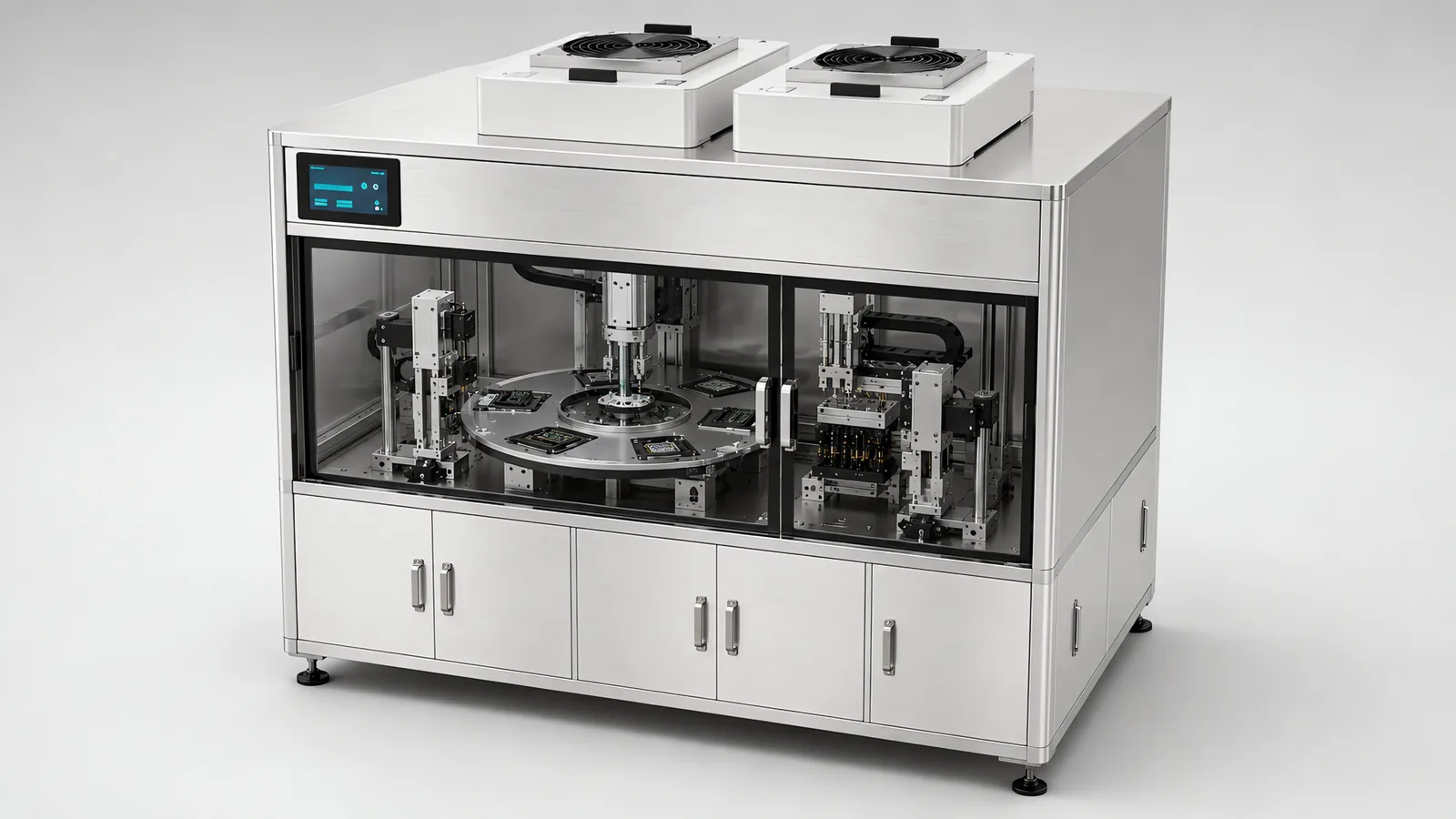
Motionwell Automation builds automated test equipment in Singapore, meaning the machine around the measurement. The delivered record is a series of five cleanroom ATE variants for electronics manufacturers, each carrying 4 to 6 fan filter units that hold an ISO Class 7/8 environment over the test fixtures, multi-station circular transfer, and test sequences covering connector insertion and withdrawal force, cable bend fatigue, and multi-point sensor functional verification. One build in that series is a cleanroom-compatible electronic tester for semiconductor devices with automated docking, thermal cycling and data logging. Collaborative-robot loading holds plus or minus 0.05 mm at the test fixture interface, calibrated against a reference pin at the start of every batch, and force, displacement, resistance and continuity are logged per serial number and exported by batch for Cp/Cpk study. Machines are designed, assembled and tested at our Woodlands Link facility, and the company has delivered more than 150 special purpose machines since 2014 under ISO 9001:2015 and bizSAFE Level 3.
Load cells, displacement sensors, meters and cameras are bought in. What we design and build is the handling, the fixture and the contacting, the sequencing, the environment inside the enclosure, the reject path and the data route into your quality system. Calibration certificates traceable to national standards come with every critical instrument in the installation qualification pack. Sealed-part integrity is a different machine again, built around a dwell time, and it is covered on the leak testing machines page.
The station-by-station build of one machine is in the cleanroom ATE case study.
What Is an Automated Test Equipment Machine, Beyond the Instrument?
It is tempting to specify an ATE around the instrument, and that is the wrong end to start from. Four subsystems make up the machine, and the instrument is usually the part that arrives with its uncertainty already characterised. A meter or a load cell arrives with a specification and a certificate. Everything around it arrives with neither, and that is where the project is decided.
| Subsystem | What it has to do | How it fails | What acceptance evidence looks like |
|---|---|---|---|
| Handling | Get the unit from a tray, pallet or conveyor into the nest, in the right orientation, without damaging it | Presents the unit slightly differently each cycle, so the reading moves while the part does not | Placement measured at the fixture interface, not quoted from the robot datasheet |
| Contacting | Make the mechanical and electrical connection the test needs, at the same force and geometry every cycle | Wears, oxidises, loosens or goes intermittent, and the drift arrives well before the failure | Repeat measurements on one reference unit across a long run, not one demonstration |
| Sequencing | Run the steps in an order that is safe and diagnostic, and stop when the answer is known | Advances on a timer, so an incomplete stroke still produces a plausible-looking number | Every motion confirmed by a sensor |
| The record | Bind every number to a unit identity and deliver it intact to the quality system | Ends as a file on an HMI memory card that nobody exports | A dataset the quality team can run a capability calculation on without retyping anything |
The pattern is that uncertainty accumulates upstream of the meter. It is the same argument made on our inline dimensional measurement page, where a sensor reporting 0.01 mm per pixel is still not a 0.01 mm gauge, because part presentation, fixture wear and temperature all sit between the pixel and the dimension. A tester has that stack with contact resistance and applied force added to it.
The delivered machines use two handling arrangements. The cleanroom series has a collaborative robot moving specimens from trays into pallet nests on a circular transfer loop. The single-station semi-automatic tester uses a vertical pneumatic cylinder to bring the test head onto the product, with a lateral gripper holding the specimen tail for bend or insertion motion. In both arrangements, the PLC advances on confirmed end-of-stroke and records force, displacement, resistance and continuity against the serial number.
Why Do Contacting and Fixturing Decide Long-Run Reliability?
Because the fixture is the datum for every number the machine produces, and it is the part of the machine in physical contact with the product on every single cycle. A tester that passes its factory acceptance test and drifts in month four is often drifting at the contact, and the contact is the place to look first.
Start with the nest. On the delivered ATE series the specimen nests are machined from nylon PA66 and POM, for two specific reasons. Surface resistivity above 10^12 ohm keeps the fixture from loading or shorting the device under test during resistance and continuity measurement, and a non-metallic nest does not shed conductive particles into a Class 7/8 envelope. What that costs is worth stating: engineering plastics creep under sustained clamping load, so the nests are consumables with a defined replacement interval.
| What wears | How it shows up in the data first | What it looks like when ignored | Countermeasure |
|---|---|---|---|
| Contact surfaces and probe tips | Slow upward drift in measured resistance across a run | Intermittent continuity failures blamed on the product | Reference unit measured at a fixed point in the rhythm, with the result logged |
| Nest and locating features | Force readings widen in spread before the mean moves | A capability study that quietly degrades between quarters | Replacement interval set from observed wear, plus a datum check after every fixture change |
| Quick-change mounting and dowel pins | Step change in results immediately after a changeover | Batch-to-batch differences attributed to the material | Re-verify against the reference artefact after every changeover, not once a week |
| Pneumatic seals and regulators | Applied force drifts with supply pressure and temperature | Force limits widened until everything passes | Regulated air preparation at each valve bank, with the set pressure recorded |
| Cabling and connectors to the instrument | Noise floor rises, marginal units start flipping verdicts | A rising retest rate nobody can explain | Continuous-flex cable rated for the travel, strain relief, and a documented harness check |
Two design rules follow. Re-verification belongs in the production rhythm: the delivered machine calibrates its loading against a precision reference pin at the start of every batch, with the offset stored in the PLC for compensation, which is why insertion-force readings stay comparable from one batch to the next. And changeover has to be repeatable as well as quick. Fixture changeover between connector types on that series is tool-free and takes under 2 minutes using a quick-change mounting system with dowel-pin alignment, and the dowel pins do the important half of that work.
Then there is an item often missing from a quotation: the consumable schedule. Contacts, nests, seals and coupler halves all have a wear interval, and a specification that lists none of them has moved a running cost off the capital sheet without removing it. Ask for four things before signing: the consumable list, the replacement interval for each item, the re-verification routine an operator runs on shift, and which spares you should hold in Singapore. The same discipline applied to robot tooling is on our end of arm tooling page.
The contact map is a useful starting point for a functional test fixture, while a tensile testing station needs its gripping and strain-measurement arrangement defined. Electrical stress testing adds another set of interfaces: hipot testing equipment needs controlled access, connection verification and a clear completion state.
Other measurements require different fixtures. A vibration testing machine includes the fixture in its dynamic system; eddy current testing depends on probe presentation and scan coverage. For helium leak testing, the fixture and station plumbing become part of the gas path being verified.
PCB contacts need board support, probe selection and a revision-controlled recipe. PCB test fixture design distinguishes contact failure from product-test failure.
An electronics joint needs its specified electrical/function result, not only visual confirmation. solder-joint test requirements connects those tests with the soldering process record.
How Does Multi-Station Transfer Stop the Slowest Test Setting the Rate?
It works by making the machine’s cycle the longest single station. On a single-station tester, a unit sits in one nest while continuity, force, fatigue and functional checks run in series, so one long functional check sets the rate for everything behind it. Split the tests across stations on a transfer loop and each station works on a different unit at the same time, so the machine indexes at the longest station plus the transfer move.
| Architecture | Cycle is set by | Suits | What it costs |
|---|---|---|---|
| Single station, tests in series | The sum of every test on the unit | Low volume, high mix, development and pilot work | The slowest test sets the rate for the whole machine |
| Multi-station transfer loop | The longest single station plus the index move | Several short-to-medium tests on a repeating unit | Station count is fixed by the loop geometry; adding a test means re-timing the ring |
| Offline rack or bank | Nothing on the line; units dwell in parallel off the loop | Long-dwell work such as burn-in, soak and extended thermal exposure | Units leave the flow, so the record has to survive the handoff |
The delivered cleanroom machines use a circular belt transfer with pallet-based carriers. Pallets circulate around the loop, stop at each station on pneumatic stopper pins, and carry RFID tags in the pallet body so the PLC knows which specimen is where and what has already been done to it. The circular layout returns every pallet to one load and unload station, so one collaborative robot serves the whole machine and only one opening has to be made in the cleanroom enclosure.
Being specific about the limit matters more than describing the benefit. Buffering pallets decouples station cycle times only within a few seconds of each other. A test needing minutes does not belong in the ring, and putting it there turns a balanced loop back into a machine whose rate is set by one station. That is the real boundary of this architecture, and the first thing to check against your own test list.
Two questions settle the station count before anyone draws a layout. Which tests are genuinely independent, meaning they can run on different units at the same time without one disturbing another? And which tests change the unit, meaning fatigue, stress or thermal exposure that has to happen in a fixed order? The first sets how much parallelism is available. The second sets where in the ring each station has to sit.
How Should a Test Sequence Be Ordered, and When Should It Exit Early?
Order the sequence by what each step can rule out and by what each step does to the unit, then decide separately whether a failure stops the run.
Three ordering rules do most of the work. Put the checks protecting the machine and the unit first, so presence, orientation, seating and continuity are confirmed before anything applies force or power. Put cheap discriminators ahead of slow expensive ones, because a unit failing a quick check should not consume a slow station. And put anything that stresses, cycles or ages the unit as late as the test plan allows, because a measurement taken after a fatigue or thermal-cycling step is a measurement of a different unit from the one that entered.
Early exit is then a policy decision, and it has a real trade in it.
Stop on first failure gives back station time and keeps the loop moving, which is what production wants once the failure modes are understood. What it costs is diagnosis: a unit that fails an early step never generates data for the later ones, so the engineering team loses the correlations that would have shown which failure modes travel together.
Run the full sequence regardless produces a complete record on every unit, which is what an engineering build, a qualification run or a yield investigation needs. What it costs is throughput, and on a loop it costs the rate of every unit behind the failed one too.
The workable answer is usually both, selected by mode. Production mode exits early and logs the failing step with the measurements taken up to it. Engineering mode runs everything. Whichever mode was running has to appear in the record, because a dataset mixing complete and truncated units without saying which is which cannot be analysed later.
One mechanical rule underpins all of it, and it is worth insisting on in the specification. Advance the sequence on confirmed position, not on elapsed time. Every pneumatic cylinder on the delivered machines carries a magnetic reed switch so the PLC advances only on confirmed end-of-stroke, because a connector that is not fully seated still produces a plausible-looking force reading. Timed sequencing is simpler to program and slightly faster. It also produces the class of wrong answer that looks exactly like a right one.
A clean edge alone does not establish an undamaged populated board. post-depaneling board checks connects separation conditions with the specified final function tests.
Should the Clean or Thermal Envelope Sit Inside the Machine or in the Room?
It belongs inside the machine, whenever the volume that has to be controlled is the test area. That is the call on the delivered ATE series: 4 to 6 fan filter units sealed into the enclosure ceiling hold ISO Class 7/8 over the test fixtures and the handling area while the machine stands in a normal factory bay with no classified facility around it.
| Control in the room | Control inside the machine | |
|---|---|---|
| What is conditioned | The whole space, including people, benches and traffic | The enclosure volume over the fixtures |
| Fits when | Several machines and operators share one controlled environment, and product moves between them | One process step needs the condition, and the rest of the plant does not |
| Running cost | Air handling for the full room volume, continuously | Fan filter units and their filter changes on one enclosure |
| Access | Gowning, airlocks and a materials route | An enclosure door, an interlock and a loading opening |
| The machine’s own contribution | The machine is a particle source inside the space you paid to keep clean | The same problem, concentrated where it is easiest to design against |
| Where it goes wrong | The room passes at rest and fails while the machine runs | Downflow blocked by tall fixtures, cable trays or overhead tooling |
For scale on the room side, ISO 14644-1 allows 352,000 particles at 0.5 micrometres and larger per cubic metre at Class 7, and ten times that at Class 8. The machine has to fit inside that budget alongside the operators and the product, which is the argument for designing the mechanism not to shed in the first place, so nobody has to clean more often.
Four details decide whether an in-machine envelope holds in production. Downflow needs a clear path over the fixtures, because tall tooling and badly placed cable trays create shadows the flow does not reach. There has to be filtered return at the enclosure base. Differential pressure monitoring has to be visible, so anyone can see the enclosure is still positive against the room. And sampling ports have to exist, so a particle counter can verify the class without dismantling anything. Pneumatic exhaust is the trap: a standard cylinder with a muffler vents into the enclosure on every stroke, at the moment and position the tooling sits over the product, which is invisible on a schematic and obvious on a particle counter. Exhaust gets ducted out of the clean zone entirely. The wider treatment is in our cleanroom machine design guide.
Thermal exposure follows the same logic with different physics. One build in the delivered series runs thermal cycling inside the machine, which is the right call when only the unit under test needs the excursion. Two consequences come with it. The fixture and the contacting have to hold geometry across the excursion, because a nest that grows and a probe that does not will change the contact force with nothing alarming. And the record has to carry the thermal step, so a measurement can be read against the condition it was taken under.
Verification belongs in performance qualification, and the number that matters is taken while the machine runs at production speed with the axes moving and the cylinders firing. At rest, almost any machine passes.
What Gets Logged Per Unit, and How Does It Reach the Quality System?
The record is written per unit, never per batch, and bound to an identity that survives the trip. On the delivered machines the PLC logs force, displacement, resistance and continuity in real time and exports by batch number, by serial number, or by test parameter, so a process capability study can be run without anyone retyping anything.
| What the record carries | Why it is there | What breaks without it |
|---|---|---|
| Unit identity | Ties every measurement to one physical unit | Results exist but cannot be traced to product, so a containment decision has no boundary |
| Measured values, not just the verdict | A verdict throws away the distance to the limit | You can count failures but cannot see drift approaching the limit |
| The limits in force at the time | Limits change; records do not travel with a memory | Old data silently compared against new limits |
| Station and fixture identity | Failures often cluster by station or by nest | A drifting fixture looks like a drifting product |
| Recipe or program version | The sequence is part of the measurement | A discontinuity in the trend with no physical cause |
| Timestamp on one time source | Ordering events is the whole question in an investigation | Two devices on one machine disagree by minutes after a year |
| Sequence mode and step reached | Truncated and complete runs are not the same dataset | Mixed populations analysed as one |
Getting it out is the second half. The delivered series exports CSV for offline analysis and offers OPC UA connectivity, so the plant’s own SCADA or historian reads the tester without the tester being rewritten for each system it has to feed, with control limits and alarm thresholds configurable per test parameter through the HMI. Both halves are deliberate. A published address space survives a change of analysis tool on the plant side without the machine program being reopened, and a file export keeps the shift’s results recoverable on the day the network is not there. Where the same records feed a plant availability and quality metric, the mapping is in our explainer on what OEE actually measures.
Two constraints attach to that data path, and both belong in the specification.
Regulated lines. Where the product is regulated, 21 CFR Part 11 clause 11.10(h) asks for device checks on the validity of the data source, which in equipment terms means the record should carry which device produced the reading and whether it was in calibration at the time. What that asks of a PLC and an HMI is on our electronic device history records page, and the route that gets instrument certificates into the installation pack is on the computer system validation page.
Network exposure. A tester connected to a plant system is an attack surface as much as a data source, so the connection gets segmented. Our scope there is the zone design, the conduit rules and the account and role configuration, and the reasoning is set out in our note on IEC 62443 industrial cybersecurity.
When integrating a hardness instrument, save the scale and test position with the value. hardness instrument records explains the method and handling requirements.
A shock test needs completion status and a valid measured pulse before assigning a product result. The shock-test instrument coordination defines those evidence stages.
Dispensing complete is not a finished-product pass. post-potting assembly tests identifies mixture, cure and electrical/function checks that need their own result records.
Crimp height, forming evidence and finished electrical requirements answer different questions. crimp quality verification defines them for the intended terminal/wire combination.
Insertion evidence and finished electrical function are separate checks. inserted-pin test records associates the pin/board revision and location with those results.
How Do You Prove the Machine Agrees With the Bench Method It Replaces?
This is the acceptance argument, and it is a different question from whether the machine works. A machine can index, contact, measure and log perfectly and still report a number that does not mean what the laboratory number meant. Correlation closes that gap, and it belongs in the acceptance protocol before the machine is built.
The method is a paired comparison. Take a set of units spanning the working range that deliberately includes marginal ones, measure each unit by the existing bench method and on the machine, and compare the pairs. Look at two things separately: the bias, meaning whether the machine reads consistently high or low, and the spread, meaning whether it agrees tightly or loosely. A machine with a known, stable bias is usually workable. A machine with a wide spread is not, whatever its average says.
Three conditions decide whether the study is worth anything.
The first is enough of the population. A correlation demonstrated on a handful of good units has been demonstrated on the wrong population. The units that matter are the ones near the limit, because those are the ones where a small disagreement changes a verdict.
The second is coverage across the things that vary. Repeat the comparison across shifts, across a fixture change and after a changeover, because a correlation that holds for one hour on one nest has not been tested against the machine’s real life. This is the same reasoning as the reference-pin calibration at the start of every batch: agreement is a property that has to be re-established, not a property that was established once.
The third is a stated share of the tolerance. Ask your quality system what share of the tolerance band the measurement system is allowed to consume, and size the fixture, the contacting and the instrument backwards from that number.
Where the machine and the bench genuinely disagree, the cause is usually mechanical and explainable. Rate of approach is the clearest example from our own work: the button actuation force tester drives a load cell on a servo screw axis at 0.05 mm per second, deliberately slow, because pushing faster lets the dynamic response of the mechanism contaminate the reading and what you record is the rig. Fixture compliance, seating depth, hold time before reading and the temperature the part happens to be at all do the same thing in smaller amounts. Each can be measured and designed for. None can be argued away at a factory acceptance test.
One boundary is worth naming while the protocol is being written. The correlation study establishes that the machine agrees with your bench method; the calibration chain behind each instrument is a separate trail, held by your metrology function and evidenced by the certificates that ship in the installation qualification pack.
Thickness instruments need valid readings associated with the correct item or strip position. Review thickness-test data validity when defining instrument result states.
Spring checks need load at defined positions and a controlled loading history. spring load and length testing separates production measurements from fatigue qualification.
A normal forming curve cannot replace every joint-function test. formed-joint verification connects riveting setup, process limits and the required final checks.
A sensor-based test needs the device-specific value structure and measurement validity. IO-Link sensor test data reviews IODD, scaling and verification after device replacement.
Flexible packaging needs the failure mechanism named before selecting a test. pouch seal test selection distinguishes seal strength, visible defects and whole-package leakage.
Ultrasonic instruments need qualified coupling and known scan coverage. ultrasonic testing integration distinguishes thickness calculations, flaw tasks and unavailable acquisition.
How Do Failures Get Segregated After the Verdict?
A verdict nothing acts on is not a test. The reject path is part of the machine, and it needs designing with the same care as the measurement.
Segregation by class is the requirement that gets underestimated. A unit that failed continuity, one that failed insertion force and one flagged for engineering review usually have different destinations: one is retested, one goes back to assembly, one is quarantined for analysis, and only some are scrap. On the delivered ATE the loading robot sorts tested units by result at the same station it loads from, so segregation by class is a matter of where the robot places a unit. Where a single destination is enough, the pattern is a pneumatic pusher into a quarantine bin downstream of the deciding station, as built on our filling and sealing platform. Where destinations differ by class, a robot pick-off places units separately, the same choice set out on our machine vision inspection page.
Four requirements travel with the reject path regardless of which mechanism you choose.
The reject device needs a sensor proving the unit left the flow. A stuck pusher passes failed units downstream while the log still records a rejection, which leaves the record disagreeing with what actually left the line.
The bin is locked and monitored: key-switch access, a full-level sensor and a documented count before it is emptied. A quarantine bin anyone can reach into is not quarantine.
Rejects are reconciled against the batch, so every unit that entered is accounted for as passed, failed, quarantined or still in the machine. Counts that do not close are how a containment decision loses its boundary.
And the retest policy is written before the machine is built. Whether a failed unit may be retested, how many times, under whose authority, and whether the retest replaces or accompanies the original record, are quality decisions. Settle them at specification stage, because the data model has to carry the answer.
When Is a Custom ATE the Wrong Purchase?
The test itself is not defined yet. With no written limits, no agreed sample set and no baseline distribution from the current method, automating produces numbers faster without making them mean more. Define the test, then automate it.
The dwell is long. Burn-in, soak and extended thermal exposure over minutes or hours belong on an offline rack or a bank, not in a transfer loop. The circular architecture buffers seconds, and building a ring around a long-dwell test wastes the loop.
A bench instrument and an operator already make rate. Where volume is low, the mix is wide and the current method meets demand, automation buys consistency. That is sometimes worth buying on its own, particularly where operator-to-operator variation is contaminating a capability study, but the argument has to be made explicitly.
The requirement is a laboratory instrument. Where what you need is the instrument itself and not a production station around one, that is an instrument purchase.
One high-volume part number, indefinitely. A reprogrammable loading device earns its place when the mix changes. Where one variant runs all day for years, a dedicated hard-automation handler is faster per cycle, and the flexibility of a collaborative arm is flexibility you are not using. The wider version of that comparison is on our cobot versus industrial robot page.
The environment was not on the specification. An enclosure holding a particle class, an ESD-controlled handling chain and a thermal excursion is a different machine from one without them, and finding that out after the frame is welded is expensive. ESD control runs in parallel with everything else on an electronics build: grounded workstations, ionizers and handling protocols for components that fail silently.
What Has to Be Settled Before Anyone Draws the Machine?
Six inputs, and each one moves the price.
- The test list, with limits: every test, its measured quantity, its limits, its dwell time and whether it stresses the unit. This sets the station count and the architecture.
- The unit, with a drawing: geometry, mass, variants, how it is presented today, and what contacting the test needs. Fixture design starts here.
- Sustained rate and shifts, in units per hour held across a shift and never as a peak figure. Rate plus dwell decides whether a loop or a single station is the right shape.
- The mix and the changeover frequency. List the variants sharing the machine and how often they change. That sets the recipe structure, the need for quick-change fixtures and the checks required before the next batch starts.
- The environment: general industrial, a particle class, ESD control, a thermal excursion, or a combination. This changes materials, finish, cabling, lubricant, exhaust routing and the qualification scope.
- The data destination: which system receives the records, in what format, over what connection, and whether the line is regulated.
All six move cost. Station count, contacting complexity, how many variants one fixture set must cover, the depth of seating and grip verification, the environmental scope and the qualification documentation each change what the machine takes to build, which is why two machines that look identical on a layout drawing can differ by a wide margin on decisions taken before anything is machined.
Lead time runs 16 to 24 weeks from concept approval to factory acceptance testing on a standard build, and 24 to 32 weeks where cleanroom compatibility or full validation documentation applies. Design, fabrication, assembly and testing happen at Woodlands Link with an in-house design team of eight, so a Singapore buyer attends the factory acceptance test without flying to it. That matters more on a tester than on a conveyor, because a fixture gets adjusted against real units and those adjustments happen in hours when the builder is in the same industrial estate. The delivered work sits in context on our electronics and semiconductor automation page, and the sample-handling and instrument-tending architecture for regulated labs is on our laboratory automation page.
Frequently Asked Questions
What is the difference between automated test equipment and a test instrument?
The instrument measures. The ATE is everything that has to happen for the measurement to mean something on every unit. A load cell, a meter or a data acquisition card arrives with a specification and a certificate, and it is usually the least uncertain part of the machine. Around it sit four subsystems that arrive with nothing: handling, which puts the unit into the nest the same way every cycle; contacting, which makes the mechanical and electrical connection with the same force and geometry; sequencing, which runs the steps in a safe and diagnostic order; and the record, which binds every number to a unit identity and delivers it to your quality system.
How do you prove an automated tester agrees with the lab instrument it replaces?
By measuring the same units both ways and comparing the pairs, not by demonstrating that the machine runs. Take a set that spans the range and includes marginal units, run it on the bench method and on the machine, and look at both the bias and the spread. Repeat it across shifts and across a fixture change, because a correlation that holds for one hour on one nest has not been tested. Where a difference is real, it is usually explainable: rate of approach, fixture compliance, seating, or the temperature the part happens to be at. Name the sample set in the acceptance protocol before the machine is built.
What maintenance does an automated test fixture actually need?
More than a quotation usually says, and it is worth pricing at concept stage. Contacts and nests are consumables: they wear, they oxidise, they loosen, and the drift shows up in the data before it shows up as a failed unit. On our cleanroom automated test equipment the engineering-plastic nests are treated as consumables with a defined replacement interval, and the cobot loading is calibrated against a reference pin at the start of every batch. Ask any supplier for the consumable list, the replacement interval for each item, the re-verification routine an operator runs on shift, and which spares you should hold locally.