
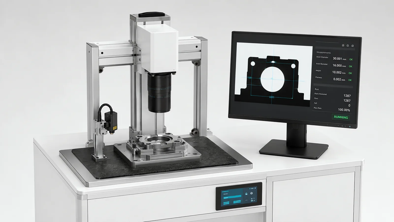
Motionwell Automation builds inline dimensional measurement systems in Singapore, meaning stations that put a number in millimetres on every part while the line runs, and never a verdict about how the part looks. The delivered record includes a copper-plate thickness measurement machine built around laser triangulation, a laser displacement sensor measuring cap height on a GMP filling and sealing platform, and a vision-guided sensor panel assembly line where the camera measures the panel’s actual X, Y and theta offset and corrects the robot inside 50 ms while the cell holds plus or minus 0.01 mm repeat accuracy. Machines are designed, assembled and tested at our Woodlands Link facility, and the company has delivered more than 150 special purpose machines since 2014 under ISO 9001:2015 and bizSAFE Level 3.
What we supply is the station: the fixture and the datum, the sensor selection, the optics and the light, the trigger and the timing, the calibration routine an operator can run on shift, and the path the number takes to your quality system. Calibration certificates traceable to national standards come with every critical instrument in the installation qualification pack.
The general capability, meaning camera and lens selection, lighting geometry, smart camera against PC-based, reject actuation and the false-reject trade-off, is on our machine vision inspection page. Judging appearance is a different problem with a different design; measuring a dimension is what follows.
What Is the Difference Between Measuring a Part and Inspecting It?
The difference is what leaves the station, and it decides everything downstream of it.
An inspection station returns a verdict. A measurement station returns a quantity that has to carry the same meaning next month, on a different shift, against a reference somebody outside the project can point at. Once you have committed to producing a number, you have committed to defending it.
| Appearance inspection | Dimensional measurement | |
|---|---|---|
| What leaves the station | A verdict, plus a score behind it | A value in millimetres, plus the limits it was checked against |
| What sets the design | The defect you have to catch | The tolerance you have to police |
| What it is referenced to | Good and bad examples you collected | A datum on the part and an artefact you can re-measure |
| What “correct” means | Agrees with an experienced inspector | Agrees with a reference, within a stated uncertainty |
| Typical failure in service | Changed lighting or presentation causes false rejects or missed defects | Drift biases the reported dimension and the resulting verdict |
| What it needs on a schedule | Lighting checks and a threshold review | Re-verification against an artefact, logged |
| What the evidence looks like | A reject log with images | A distribution, a capability study and a calibration record |
Drift can escape notice in either station. Appearance inspection may miss more defects without increasing the reject rate, while a dimensional gauge may continue to report plausible but biased values. Both need scheduled checks against known samples; the dimensional station also needs a traceable measurement reference and an uncertainty budget.
If the requirement includes both visible scratches and bore diameter, assess the two optical tasks separately. They may need different lighting, magnification or camera positions. Prove both tasks on the same setup before combining them into one station.
Choose the result channel from the characteristic being checked. A checkweigher measures mass, while eddy current inspection evaluates an electromagnetic response; neither supplies a dimensional measurement simply by returning a pass or fail.
For optical geometry, the 2D vs 3D vision comparison starts with the quantity and reference surface. The machine vision and computer vision distinction explains the wider production system around the algorithm. Compare Cognex and KEYENCE proposals using the same features, samples and measurement reference.
What Actually Limits Accuracy in an Inline Measurement?
Fixturing and part presentation set the limit, well before optics do. The mis-ordering is common enough to be predictable: a specification names a camera resolution and says nothing about how the part is held.
A camera cannot compensate for a part that rocks in its nest. It reads that rocking as dimensional variation and scraps good product. On a multi-station rotary assembly machine, for example, the nest design deserves more of the schedule than the vision setup, and we would machine the jig contact surfaces to a tolerance tighter than the dimension the station has to hold. That is not decoration. Every micron of slop in the nest is spent before the lens gets a chance. How the nests and the dial are designed on that class of machine is on our rotary indexing assembly machine design page.
Repeatability is also not accuracy. A figure quoted for an axis or a robot describes how tightly it returns to a taught point and says nothing about part tolerance, fixture wear or thermal drift, which is usually what you actually measure on the finished assembly. The same caution applies to a sensor datasheet.
| Error source | How it shows in the data | Where it actually gets fixed |
|---|---|---|
| Part rocks or shifts in the nest | Spread far wider than the sensor’s own noise, with no pattern | Nest and clamp design, and a part-seated sensor before the trigger |
| No defined datum on the part | Two operators or two stations disagree on the same part | The drawing, settled before the station is designed |
| Fixture wear | Slow one-directional walk over months | Hardened or ground contact surfaces, plus artefact checks that see the walk |
| Vibration from a neighbouring station | Periodic noise, present only when the other machine runs | Isolated mounting for the station |
| Ambient light reaching the field of view | Day shift and night shift disagree | Shroud the station, so factory light and daylight never arrive |
| Trigger jitter | Blur or position error that scales with line speed | Everything downstream inherits the trigger’s jitter, so fix it at the trigger |
| Soft or ambiguous edge | Result changes with light level | Backlight the feature so the edge is defined by geometry |
The practical consequence is an order of work. Define the datum, then design the fixture, then choose the sensing, then choose the algorithm. Projects that run that order backwards end up buying resolution to compensate for a nest, which does not work and is expensive. How the fixture and the presentation get designed for a robot-fed station is covered on our end of arm tooling page, and the wider cell context on robot integration services.
Why Does a Telecentric Lens Change the Answer on a Dimension?
An ordinary lens makes the measurement depend on where the part is, and a part on a production line does not sit in exactly the same place twice.
A standard lens images the top of a tall part at slightly different magnification than the bottom, so a dimensional check reads differently as the part shifts. That is perspective error, and it is harmless on a presence check and fatal on a dimension. A telecentric lens removes that change: within its design range, moving the part along the optical axis does not change how large it appears. The dimension you read stops being a function of how the part happens to be sitting.
The cost is geometry. A telecentric lens restricts you to a field of view no larger than the lens itself, so a wide part means a physically large and expensive lens, or several cameras, or indexing the part under one camera in several positions. That decision has to be taken at concept stage, because it changes the machine frame.
Three optical constraints then travel together, and fixing any two determines the third.
- Resolution at the part: field of view width divided by sensor width in pixels. You need roughly three pixels across a feature to detect it reliably, and five or more if you intend to measure it. A single pixel is indistinguishable from sensor noise.
- Depth of field: closing the aperture deepens focus and cuts the light reaching the sensor, which pushes you toward more illumination or a longer exposure. Depth of field also shrinks as you magnify, so a warped part can drop out of focus at its edges while the centre stays sharp.
- Working distance: the lens has to clear the fixture, the gripper swing and the operator’s hand, so the optical layout freezes with the machine layout.
| Field of view width | Sensor width | Resolution at the part | Pixels across a 0.1 mm feature |
|---|---|---|---|
| 100 mm | 2448 px (5 MP) | 0.041 mm/px | ~2.4 |
| 100 mm | 4096 px (12 MP) | 0.024 mm/px | ~4.1 |
| 200 mm | 5472 px (20 MP) | 0.037 mm/px | ~2.7 |
| 400 mm | 5472 px (20 MP) | 0.073 mm/px | ~1.4 |
The bottom row is the one worth arguing about in a specification. A 0.1 mm feature across a 400 mm field does not resolve on one camera, whatever the marketing says, and the three answers that do work are to split the field between cameras, index the part, or move the part under a line-scan camera. The full sizing arithmetic, with more rows and the electronics-specific version, is in our guide to vision inspection sizing.
For the camera-based branch, use the machine vision lens guide to compare the view, height variation and pixel sampling. The accepted gauge still needs the calibration and capability evidence described here.
Which Sensing Arrangement Suits Which Dimension?
Match the physics to the feature before matching a brand to the budget. A camera infers an in-plane dimension well and infers height badly; a displacement sensor does the reverse.
Backlight silhouette suits an in-plane dimension. Light behind the part turns the outline into a hard edge, and the contrast becomes independent of surface colour, print, gloss and the state of the operator’s cleaning cloth. The measurement stops depending on how the part looks and starts depending only on where its edge is, which is the whole point. Pair a backlight with a telecentric lens and both of the large error sources, surface appearance and perspective, are designed out.
| What you need to measure | Arrangement | Why it suits | Where it stops working |
|---|---|---|---|
| Outline, width, gap, hole spacing in one plane | Backlit silhouette, telecentric lens | Edge defined by geometry, magnification independent of part position | Features inside the outline, or a part too wide for the lens |
| Edge position on a printed, coloured or glossy part | Backlight | Contrast is independent of surface colour | Translucent material that lets light through the body |
| Height, step or seating depth at a point | Laser triangulation displacement sensor | Measures height directly, inferring nothing from a 2D image | Steeply angled, mirror-like or deeply recessed surfaces |
| Thickness of a plate or sheet | One displacement sensor referenced to a known surface the part sits against | Removes the part’s own position from the result | A part that does not sit flat against the reference surface |
| Profile across a whole section | Laser profile sensor with the part moving under it | Gives a section, so a local defect cannot hide between points | Slow relative to a single-point sensor, and needs controlled motion |
| Coplanarity across many points, such as connector pins | Structured light or laser profiling | A projected pattern deforms on the surface and triangulation gives height | Deep shadows and occlusion on tall features |
| In-plane pin position | Backlit or dark-field 2D imaging | It is a 2D problem, so solve it in 2D | Says nothing about coplanarity, which is a height problem |
| Anything under a coating, inside the material or sealed | Not an optical measurement at all | Vision cannot see through material | Needs X-ray, ultrasonic, or a different test entirely |
Two delivered examples show the split. A copper-plate thickness measurement machine uses a laser displacement sensor, because triangulation reads height along the beam while a 2D image can only infer it, and because the division of labour is part of the answer: the axis positions, the sensor judges, and neither is asked to do the other’s job. On our capping and sealing systems, cap height is taken by laser displacement for the same reason, since one direct geometric reading says both whether a cap is present and how far down it went, where a camera looking from above needs a second view before it can tell a missing cap from a high one. Neither of those is a vision problem, and treating them as one would have cost accuracy for no benefit.
Where a surface defeats triangulation, because it is mirror-like or transparent, the answer moves to sensing principles beyond the ones in that table: confocal chromatic, interferometric or specular arrangements built around the reflection instead of against it. Bring that surface to the concept review with a real sample, because the sensing principle changes the station and it is settled there.
For thickness, define both surfaces and the reference arrangement. thickness measurement chain explains why one surface-position reading may not establish the required quantity.
A thickness channel needs material velocity and valid returned signals. ultrasonic measurement validity includes a simple pulse-echo calculation and acquisition-failure checks.
How Do You Set a Dimensional Gauge Re-Verification Schedule?
Set the check interval from the measurement risk, observed drift and events that can disturb the station, such as a fixture change or maintenance. Use traceable artefacts to reveal changes before production decisions rely on a biased result. Appearance inspection also needs periodic challenge samples; its checks address defect detection and false rejects instead of dimensional uncertainty.
Re-verification means putting a known object through the station and confirming it still reports what it reported before. On our cleanroom automated test equipment the cobot loading is calibrated against a reference pin at the start of every batch, so insertion-force readings stay comparable from batch to batch. The same discipline transfers to a dimensional station: a master part, a gauge block, a pin or a glass reticle, measured at a fixed point in the production rhythm, with the result logged.
| What drifts | How it shows up | What catches it |
|---|---|---|
| Lens focus or mount creep after vibration or a knock | A step change in the mean, dated to nothing anyone remembers | Artefact check with results logged against date and shift |
| LED output falling with age | Edge threshold moves slowly, so dimensions walk in one direction | Artefact trend, and monitoring light level |
| Fixture and datum surface wear | Slow one-directional walk over months | Ground contact surfaces, artefact checks, and a wear interval in the maintenance plan |
| Sensor window contamination | Increasing noise, then intermittent dropouts | Cleaning interval, and a signal-quality output where the sensor provides one |
| Temperature of part, fixture and frame | Result changes with time of day and with season | Measured drift against the artefact |
| Software or recipe change nobody recorded | Discontinuity in the trend with no physical cause | Version control on the recipe, and a change record |
Where the line is regulated, this stops being good practice and becomes a rule. 21 CFR Part 11 clause 11.10(h) asks for device checks on the validity of the data source, which in equipment terms means the record should carry which device produced the reading and whether it was in calibration at the time. What that asks of a PLC and an HMI is on our electronic device history records page, and the route that gets instrument certificates into the installation pack is on the computer system validation page.
How Do You Prove the Gauge Against the Tolerance, Not the Camera Specification?
You prove it by testing the whole station against the tolerance it is policing, with the real parts, the real operators and the real fixture. A sensor datasheet is not an answer to that question.
A sensor reporting 0.01 mm per pixel is not a 0.01 mm gauge. Resolution is the smallest step the device can report. Accuracy is how close the reported value sits to the true one. What you care about is neither of those on their own: it is how much of your tolerance band the measurement system consumes before the process gets any of it. Ask your quality system what share of the tolerance the gauge is allowed to take. That number, and never the camera specification, sizes the optics and the fixture.
The study that settles it is a gauge repeatability and reproducibility study, which we run and ship as part of the documentation package on medical device builds. Run it in this order, because the order tells you where the error lives.
- Measure one part repeatedly without touching it. This is the sensor and the algorithm alone. If that spread is already large, the optics or the lighting is wrong and nothing else will rescue it.
- Remove and replace the same part between readings. The gap between this spread and the previous one is your fixture and your part presentation. A station that passes on a bench and fails on the line often differs only in this step.
- Repeat across operators and shifts. This adds the human and the environment, and on an automated station it should be near zero. Where it is not, look for something changing between shifts, a setting, a cleaning routine or the ambient light, before you look at the sensor.
- Repeat across part lots and variants. Real parts vary in ways masters do not, and a gauge proven on one lot has been proven on the wrong population.
- Compare the total against the tolerance band, never against the sensor specification, and write the comparison down where the buyer can see it.
Then feed the result forward. On the cleanroom test equipment, force, displacement, resistance and continuity are logged per serial number and exported by batch for process capability study. That is the shape a dimensional station should copy: measurements bound to a unit identity, exported in a form the quality team can run a capability calculation on without re-typing anything.
A sharp-looking edge must also be repeatable across part presentation. Review dimensional-inspection lighting before fixing the illumination geometry for dimensional checks.
A visually polished face does not establish its flatness. lapping result measurement separates surface texture, form and the support condition used during inspection.
What Does Temperature Do to an Inline Gauge?
Temperature does more than most specifications allow for, and it acts on three things at once: the part, the fixture and the measuring frame, each with its own material and its own temperature.
A dimensional specification assumes a reference temperature. A production floor in Singapore does not hold it, and neither does a part that has just come off a moulding machine, out of a wash, or off a warm conveyor. The gauge therefore measures the part at the temperature it happens to be, which is not the temperature the drawing assumes, and the difference lands in your tolerance budget whether or not anybody accounted for it.
The nearest thing we run to this today is a placement loop. On the vision-guided sensor panel assembly line, the closed-loop compensation cycle runs in under 50 ms and corrects for panel positioning drift, thermal expansion of the conveyor, and tray-to-tray variation in component position, so the thermal term is measured every cycle instead of being assumed away. The same reasoning transfers to a measurement station: thermal drift measured and cancelled every cycle.
Four things to settle before the station is drawn:
- Where the heat comes from. Cameras and their lighting run warm, upstream processes send parts in warm, and a fan-filtered enclosure has its own thermal behaviour.
- Whether the part is allowed to equalise. A buffer that gives a part a known dwell before measurement is often cheaper than compensating for its temperature.
- Whether the sensor and the datum share a thermal path. If the sensor mount and the fixture warm together they move together and much of the error cancels. On separate structures, it does not.
- Whether you measure drift or model it. Measuring a master artefact at intervals catches drift nobody modelled. A correction factor catches only what somebody thought of.
The general rule for this class of station is that the engineering problem in inline measurement is repeatability across thermal drift, vibration and part-to-part variation, and never raw accuracy in a laboratory. Measurement stations need thermal compensation, isolated mounting and a calibration routine an operator can actually run on shift.
What Do You Do With the Number Once You Have It?
A reject is the weakest thing you can do with a measurement, because it throws away everything the number knew except its sign.
Three better uses, in increasing order of value.
Trend it. A dimension moving steadily toward a limit is a maintenance ticket you can raise before you make a single reject. A pass and fail flag tells you nothing until the day it fails; a trended measurement tells you what is coming and roughly when. The copper-plate thickness gauge we delivered was specified on that reasoning: it turns pass and fail into a trend. The plant-level version of the argument is in our note on what OEE actually measures.
Feed it back into the process. A measurement that adjusts something is worth more than one that files a report. Two delivered examples: the panel alignment station uses motorised XYZ linear modules with micrometre resolution to compensate for panel warpage and edge trim tolerance that would otherwise propagate into every downstream station; and on the SCARA panel assembly line the vision system calculates the X, Y and theta offset and sends it to the robot controller over high-speed fieldbus so the placement trajectory is corrected in real time. The same shape is what we specify on a filling line, where a checkweigher reading every container feeds the dosing controller so it trims the piston stroke as density drifts through the shift, set out on the volumetric versus gravimetric filling page. In each case the measurement changes the next action instead of only recording the last one.
Bind it to the unit. A number attached to a serial number is evidence; the same number in a daily average is a statistic. On a multi-station rotary assembly machine we would put a load cell on every press station and record the full force-displacement curve against the part serial number, so a fault is attributed to the station that caused it. Specify a dimensional station the same way.
What happens mechanically when a part does fail, meaning reject actuation, the confirmation sensor that proves the part actually left the line, and the shift register that carries a result along with its part to the reject point, is common to any inline decision and is covered on the machine vision inspection page.
When Is an Inline Measurement System the Wrong Answer?
Six conditions send the answer somewhere else, and any one of them is enough.
The tolerance is tighter than the presentation can support. If the fixture, the temperature and the part’s own form variation eat the tolerance before the sensor is switched on, an inline station will produce numbers that satisfy nobody. The answer there is a sample measured offline on a proper instrument, in a controlled room, against a control plan. Measuring every part badly is worse than measuring some parts well.
The feature is not accessible at line rate. Internal geometry, a dimension under a coating, or a feature visible only after an irreversible assembly step. Vision cannot see through material, and lighting does not change that.
The volume does not justify a station. Where a technician with a calibrated hand gauge and a documented sampling plan covers the requirement, that is cheaper than a machine and easier to defend.
A standard instrument already does it. Some dimensions are covered by an off-the-shelf gauge or a sensor with its own bracket, and buying one is a smaller job than designing a station. Where that is the case, the useful answer is to point you at it.
The measurement is the basis of sale. If a declared quantity is what your customer is paying for, you are in legal metrology. In Singapore the instrument used for that purpose may fall under the weights and measures regime, with pattern approval and verification attached, which restricts which instrument you may install and how it must be checked in service. Settle that before the sensor is specified, because retrofitting an approved instrument into a machine designed around an unapproved one is expensive.
The real problem is the process. Measuring more often does not narrow a distribution. If the parts are out of tolerance, a gauge tells you so faster and more expensively than the current method does. That can still be the right purchase, when speed of detection is what you are buying, but it should be bought knowingly.
What Does Motionwell Actually Build Into a Measurement Station?
The station, and the parts of it that decide whether the number is worth anything.
That means the datum and fixture design, with contact surfaces drawn to the tolerance the gauge needs and machined by the shops we use for our own jigs and fixtures. It means the sensor and optics selection, argued from the physics of the feature and lit for that feature. It means the trigger, timing and PLC handshake, so the result lands inside the cycle.
And it means three things that get left out of quotations: the artefact routine and its logging, the data path with results bound to a serial number and exported in a form your quality system can run a capability study on, and the shrouding that keeps factory light out of the field of view.
Camera-to-robot calibration, where the measurement drives motion, is done as a multi-point calibration with verification runs, so accuracy holds across the whole working envelope and not only at the calibration point. Put that distinction into the specification: a single-point calibration passes a demonstration and fails an envelope.
Usually this is one station inside a machine we are building anyway: an assembly cell, a test rig, a filling line, or a retrofit whose control system we are modernising. We work from Woodlands Link with an in-house design team of eight, ISO 9001:2015 certification and bizSAFE Level 3, and machines go through factory acceptance testing here before they ship. That matters on a measurement station, because a gauge gets adjusted against real parts and those adjustments happen in hours when the builder is in the same industrial estate. The electronics-side context sits on our electronics and semiconductor automation page.
Standards Used in Machine Design and Validation
These references inform the design, testing and documentation described on this page. Each row links to its primary source and records the edition checked.
| Standard | Current edition | What it means for your machine |
|---|---|---|
| 21 CFR Part 11: FDA rule on electronic records and electronic signatures | Current eCFR text; most recent amendment to the part dated 2 March 2023 | Applies to electronic records maintained under FDA predicate rules and to the electronic signatures within its scope. Identify those records during machine specification, then design access control, audit trails, retention, accurate copies and signature binding around their intended use.Checked 7 Sep 2026 against eCFR versioner API (ecfr.gov/api/versioner/v1/versions/title-21.json, part 11), latest section amendment_date 2023-03-02 |
Frequently Asked Questions
What is the difference between a dimensional measurement system and a vision inspection system?
A dimensional station returns a quantity tied to a datum, unit and measurement uncertainty. An appearance-inspection station usually returns a defect verdict against agreed examples. Both need controlled presentation, lighting and periodic checks. Dimensional gauging adds traceable reference artefacts and a measurement capability study; appearance inspection uses representative good, defective and marginal samples to check detection and false rejects.
How accurate does an inline measurement system need to be for my tolerance?
Accurate enough that the gauge consumes only a small agreed share of the tolerance it is policing, and that share is a number your quality system states, and never one the camera vendor states. Resolution is not accuracy. A sensor reporting 0.01 mm per pixel is not a 0.01 mm gauge, because part presentation, fixture wear, temperature and edge definition all sit between the pixel and the dimension. Bring the tolerance to the concept review. The optics, the fixture and the sensor are then sized backwards from it.
How often does an inline gauge need re-verifying?
Often enough that drift is caught by the schedule. The practical pattern is a calibrated artefact measured at a fixed point in the production rhythm, logged. On our cleanroom automated test equipment the cobot loading is calibrated against a reference pin at the start of every batch for exactly this reason. Every critical instrument also carries a calibration certificate traceable to national standards in the installation qualification pack. Set the interval from how fast the station has actually been seen to drift, then tighten or relax it on the evidence.