
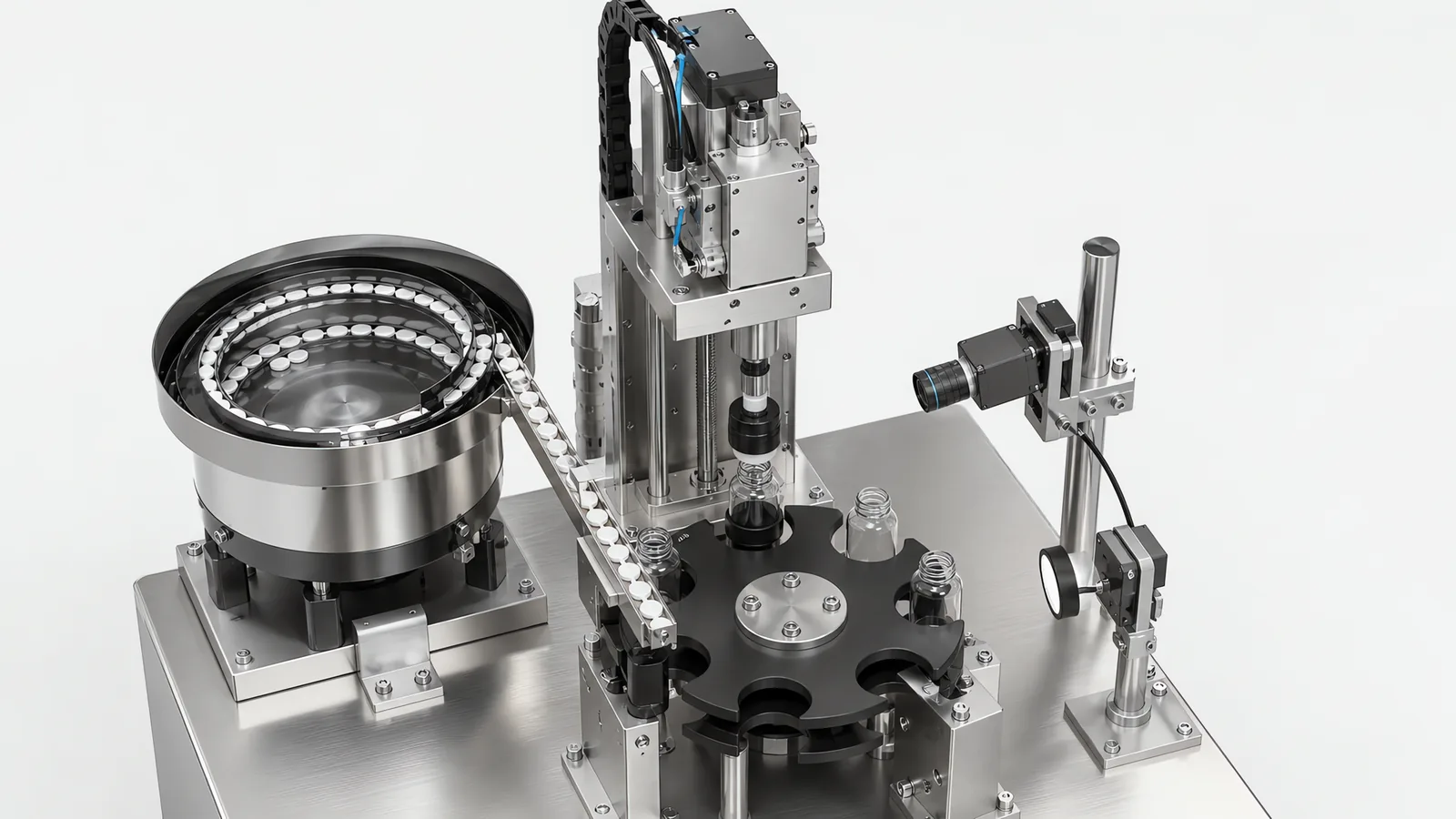
Motionwell Automation designs and builds capping and sealing systems in Singapore for pharmaceutical, medical device and consumer product lines. Enquiries often reach us as a request for a bottle capping machine in Singapore and turn out to be a request for a capping station that has to sit inside an existing line. The delivered reference is our filling and sealing machine, a tray-fed platform built for a medical and pharmaceutical customer: containers come off an infeed tray, are dosed three at a time from a triple dispensing head, closed in the same machine, with fill level read by camera before they reach the outfeed tray. Throughput on that platform is set by the fill volume and by how long the closure has to be held under the head, so it is quoted against your own container and closure, and never printed as a machine rating. Its sealing station covers heat-seal, press-on and screw closures, with the seal temperature held by a closed loop on the tooling, because a heat seal is made by temperature, dwell and pressure together and an open-loop heater drifts with ambient air and with how long the machine has stood idle between trays. Container presence at each station is read by fibre optic sensing, because a timer cannot separate a missing container from a late one, and a sealing head that comes down on an empty nest puts heat and a closure onto the tray. Containers that fail inspection are rejected. The machines are designed, assembled and tested at our Woodlands Link facility, and the company has delivered more than 150 special purpose machines since 2014 under ISO 9001:2015 and bizSAFE Level 3.
Capping sits immediately downstream of dosing, so it is worth reading alongside the filling machines we build and the inline vision inspection that judges the result. The delivered build is documented in the filling and sealing machine case study.
Which Capping and Sealing Method Fits Your Container?
Closures are classified by how the seal is formed. The container finish and the closure supplier decide this before any machine question comes up, and getting it wrong is the one mistake that cannot be tuned out later.
| Method | How the seal is formed | Suits | What it needs from you |
|---|---|---|---|
| Screw capping | A chuck grips a preformed cap and rotates it onto the thread to a set torque | Bottles, jars, vials, most liquids | A torque target from the closure supplier, and a container held square against the reaction torque |
| Snap or press-on | A plunger presses the closure over the finish bead until it clicks home | Flip-tops and some medical containers | Force and depth control, because there is no torque to measure |
| ROPP roll-on pilfer-proof | A plain aluminium shell is threaded onto the finish in place by forming rollers, and a second roller rolls the pilfer band under the neck ring | Pharmaceutical liquids in glass | Consistent shell thickness and a neck finish within tolerance; the machine forms the thread, so the glass sets the result |
| Crimp seal | An aluminium seal is crimped over a stopper and the vial neck | Injectable vials, sealed after stoppering | A stopper already seated correctly; crimping a lifted stopper seals the fault in |
| Induction seal | An induction coil heats a foil laminate liner inside an applied cap, bonding it to the container land | Bottles needing a tamper-evident barrier under the cap | A compatible container material, a liner matched to it, and correct application torque so the foil is pressed flat during heating |
| Heat seal | A heated tool bonds a foil or film lid to a tray or cup flange | Trays, cups, blister formats | A clean, flat flange; product on the seal area is the usual defect source |
| Ultrasonic seal | Ultrasonic energy welds the film to the container without a hot tool | Films that scorch, filled products sensitive to heat | Joint design done at container stage |
Motionwell’s delivered sealing work sits on two machines. The filling and sealing machine closes with heat-seal, press-on and screw closures on the same platform that doses the container, with the fill level read by camera on every container. The vial capping and uncapping unit closes and opens vials with a pneumatic capping head carried by a collaborative robot. Induction sealing heads are a settled commodity, and the result there is decided by the cap, the liner and the application torque, with the head itself contributing very little, so where a line needs ROPP or induction sealing we buy a proven head and design the station around it, the same way we do with can seamers and stretch wrappers. The closure and the liner are your closure supplier’s decision, and their data sheet gives the application torque window the machine is then built to hold.
The induction sealing machine guide connects liner contact, head position and exposure time. For a designed thermoplastic welded joint, ultrasonic welding equipment uses a different energy path and tooling arrangement. Where the seal specification calls for tracer-gas measurement, helium leak testing defines the fixture, gas path and reference checks.
Product caught at the pouch mouth can affect closure. pouch seal preparation connects opening, filling and seal-window trials with final integrity checks.
Plastic/laminate and aluminium tubes can need different closure routes. tube tail-sealing choice connects material choice with tail and product inspection.
Why Is Torque Control the Centre of a Capping Machine?
For screw closures, application torque helps establish the sealing load and the force needed to open the pack. Too little can leave the seal inadequately compressed; too much can distort the liner, damage the thread or shear the tamper band. Appearance alone may miss either condition. Torque control works alongside checks on the liner, container finish and closure alignment, followed by the seal-integrity test required for the product.
The same argument runs on our assembly machines with a different fastener. On the SCARA sensor panel line, electric screwdrivers fasten to a controlled torque, because an under-tightened fastener loosens in service and an over-tightened one strips the thread or cracks the substrate. A closure fails in exactly those two directions. Torque control is the same idea applied to a cap.
That is why, where the torque record matters, the capping head should be servo-driven. A friction clutch or a magnetic clutch releases at a set torque and tells you nothing else, and it drifts as it wears. A servo head with torque feedback gives a programmable range, changed by recipe stop, plus a continuous reading of what the closure did on its way home.
One boundary worth stating. Application torque, which the machine controls, is not removal torque, which is what your customer experiences and what your QC lab measures. The relationship between them depends on the liner, the thread finish and how long the pack sits, so removal torque has to be measured on filled product, not assumed from the machine setting. We build to your application torque window and prove repeatability at factory acceptance testing. The window itself is your closure supplier’s number, validated by your own removal-torque testing.
What Does a Torque Curve Tell You That a Torque Number Cannot?
A final torque figure is one sample from a process that lasted a few hundred milliseconds. The curve is the whole process, and the shape carries the diagnosis.
A correct application has a recognisable signature: near-zero torque while the cap runs down the thread, then a sharp rise as the liner compresses, then the cutoff. Change any part of the mechanism and the shape changes before the final number does.
- Torque that rises immediately, with almost no run-down, usually means the cap started cross-threaded and jammed on the first thread.
- Torque that never rises to target within the expected angle means the thread stripped, the cap is not engaging, or the container is spinning in the holder.
- A rise that reaches target early, in fewer degrees than normal, points at a liner that is thicker than the last batch, or a closure supplier change nobody told production about.
- The same target reached with a shallow, drawn-out rise usually means the liner is missing.
This is why a servo capping station should log the curve per container. Combining torque with rotation angle turns a single value into a window, and the window catches faults that any single number lets through. Servo torque signals are free process signatures generally: on a multi-station rotary assembly machine we would put a load cell on every press station and keep the force-versus-displacement curve against the part identity, rejecting any insertion that lands outside the band. The reasoning behind that is set out in how we design multi-station rotary assembly machines.
Where the line is regulated, that log stops being process data and becomes a record. A servo torque curve kept as evidence that a cap was applied correctly falls under 21 CFR Part 11, which changes where it is stored, who can alter it and what audit trail follows it. How that split gets decided during validation is on our electronic batch record page.
How Do Caps Get Fed, Sorted and Presented?
Feeding is where capping lines lose their rated speed, and it is consistently under-scoped in quotations. The head can only apply a cap that arrives the right way up, at the right moment, in the right place.
A typical feed chain has four stages. A bulk hopper holds a shift’s worth of caps at floor level. An elevator lifts them into a sorter. The sorter, usually a vibratory bowl with a tuned track and escapement, or a centrifugal sorter for high rates, rejects caps in the wrong orientation back into the bowl and passes correctly oriented ones onto a chute. The chute delivers to a pick-off point where the chuck or a starwheel takes one cap per container.
We have built these with escapement feeding stations on assembly machines, and bowl feeder retooling with starwheel indexing is work we take on for high-mix production. The engineering reality is worth stating: a feeder tuned to an awkward closure is engineered work, and closures are not exempt from that arithmetic. A feeder that presents a wrong-way part every fiftieth cycle also costs far more than it looks like it should, because every one of those is either a jam or a reject.
Closure geometry decides how hard this gets. Plain screw caps and ROPP shells are close to symmetrical and sort well. Flip-tops with a hinge, caps with an off-centre spout, child-resistant closures with an inner shell, and trigger sprays with a dip tube are all progressively worse, and a trigger spray is not a bowl-feeding problem at all. Its dip tube tangles, so it usually needs a dedicated sorter or a robot pick from a tray. If your roadmap includes a closure like that, put it on the requirement list at concept stage. Retrofitting a second feeding technology onto a finished machine is a rebuild.
Two mechanical points that decide uptime more than feed rate does. Cap tracks need to be cleared and changed without tools, because they will jam and an operator will be standing there. And the pick-off point needs a sensor confirming a cap is actually there, so the machine skips the container instead of sending an open bottle downstream.
What Actually Goes Wrong on a Capping Station?
Capping failures are a short and repeatable list. A machine is worth buying when it catches every item on it, and each check costs money, so it is worth knowing what you are paying for.
| Failure mode | What it looks like on the floor | Usual root cause | What catches it |
|---|---|---|---|
| Cross-threading | Cap sits high, turns without tightening | Cap presented off-axis, worn chuck jaws, container not held square | Torque curve rises immediately with no run-down, plus cap height out of band |
| Cocked or skewed cap | Visible tilt, leaks under compression | Cap dropped off-centre from the chute, container not centred in the starwheel | Top-view camera measuring skew angle |
| Torque drift across a shift | Same recipe, falling removal torque at QC | Chuck or clutch wear, liner batch change, thread lubricity change | SPC trend on the logged torque data |
| Cap missing or not seated | Open container, spilled product downstream | Feeder starved, escapement jam, cap bounced out at pick-off | Cap height measurement after the head, and a no-cap-no-run interlock at the pick-off |
| Tamper band already broken | Pilfer ring separated before dispatch | Application torque too high, band bridges weak, chuck gripping the band | Top-view camera checking pilfer ring separation and tamper band engagement |
| Liner missing or displaced | Passes torque check, leaks in transit | Closure supplier batch problem | Not caught by a standard capping station; needs a dedicated cap-inspection camera before application, specified at design stage |
| ROPP thread not fully formed | Cap spins freely on a filled bottle | Roller pressure or height set wrong, shell thickness variation, glass finish out of tolerance | Formed-thread inspection plus offline removal-torque testing on samples |
| Cap backs off after release | Torque logged as correct, cap loose hours later | Liner elastic recovery, dwell too short at high speed | QC removal-torque testing on aged product |
The last two rows are the ones a machine cannot close on its own. A capping machine cannot see everything. Removal torque on aged product is a laboratory measurement, and no inline sensor substitutes for it. What the machine can do is hold the application window tightly enough that the laboratory result stays inside its own specification, and give you the data to investigate when it does not.
A closed-looking seam is not the full verification of a flexible package. pouch sealing verification separates peel-strength and leakage evidence for the required seal.
How Is Every Cap Verified, Not Sampled?
Every container on our filling and sealing machine is inspected: a camera reads the fill level on each container after dosing, and a container outside the window is flagged before the tray leaves the machine. The full verification stack we design to runs three independent checks that fail in different ways.
A cap height measurement is a direct geometric check of whether a cap is present and how far down it went, and it is fast enough to run at full line rate. The torque curve covers the application itself, as set out above, where the head is servo-driven. Then a top-view camera inspects the sealed closure for tamper band engagement, pilfer ring separation, cap presence, cap skew angle and visible defects such as cross-threading or incomplete sealing, checking multiple criteria at once and assigning one composite pass or fail result.
In that stack, failed containers are diverted to a reject position downstream of the vision station, and the reject handler should log each rejection with container serial number, rejection reason and inspection image for quality review and SPC analysis. How the cameras are specified, lit and calibrated, and how the false-reject and false-accept balance gets set, is on our machine vision inspection capability page.
State the limit clearly. None of these three checks measures seal integrity. Vision cannot see through material and cannot detect a leak; leak detection needs pressure decay or tracer gas, which is its own station with its own cycle time. What that station contains, and why the dwell time sets its rate, is on the leak testing machines page. If your product needs proof of container closure integrity and not proof of correct application, that is a separate machine on the requirement list, and it should appear in the specification from the start, because a change order after commissioning is the expensive way to add a station.
When Should the Capper Be a Separate Machine Instead of Part of the Filler?
This is the question that gets decided too late on most projects, so here is the reasoning we apply.
Keep capping inside the filling machine when one container envelope covers your whole range, the closure family does not change, and the two stations naturally share a rate. Integration is cheaper, the footprint is smaller, one control system handles the handshake, and there is no transfer between machines to lose containers in.
Split the capper out when any of these is true.
The format envelope is different. On a rotary machine the star wheel, container guides and capping chuck geometry are all tied to a container envelope. A container outside that envelope is a change part set. If your bottles share a fill volume but not a neck finish, a separate capper with its own change parts costs less over five years than forcing both through one carousel.
Closure physics differ. A line running screw caps and trigger sprays is running two feeding technologies and two application methods. That is two machines wearing one cabinet, and it will be quoted and maintained as such whether or not it is drawn that way.
Changeover has to happen while the filler keeps running. A standalone capper can be set up on the bench for the next SKU and swapped in. A capping section inside a rotary filler stops the filler.
You already own a filler that works. A common real case. If dosing is fine and closing is the problem, buying a filler to fix a capper is an expensive way round. A retrofit capping station with its own conveyor tie-in is the direct fix.
Validation scope should be contained. In a GMP plant, changing anything inside a qualified filling machine drags requalification across the whole machine. A separate capping station bounds that scope.
The rates do not match. Our filling and sealing machine doses three containers at a time from a triple head, and the sealing station has to keep pace with whatever dosing rate your fill volume allows. If the closure needs a longer dwell than the fill does, the capper needs more heads or its own carousel, and buffering between two machines is easier than balancing inside one.
Against all of this, integration wins on footprint, on cost, and on one less container transfer. Two machines mean an accumulation conveyor between them, and every transfer is a place a container falls over.
What Changes When the Capping Line Is GMP?
The mechanism does not change. Everything around it does.
Product-contact and splash-zone construction moves to stainless steel, and the grade, the surface finish and the enclosure rating stop being shop decisions. Each of the three becomes a specification line, set by your cleaning chemistry and your washdown method and fixed in the user requirement specification before design freeze, because they are what the quality team measures against the as-built documentation later. Our filling and sealing machine was built on that basis and laid out for an ISO Class 7 or Class 8 room, and the construction side is covered on the pharmaceutical packaging automation page.
Documentation becomes half the project. GMP builds ship with IQ/OQ/PQ packages, factory acceptance testing at our Singapore facility before shipment, site acceptance testing at your cleanroom, and validation protocols following ISPE Baseline Guide Vol. 5. Where the capping head logs torque, that record can be kept as 21 CFR Part 11 evidence.
On a serialised pack, the closure and the code compete for space. Specify the code content, print quality and verification rules for the product’s destination market. Medicines within the scope of the EU safety-features regulation use a unique identifier carried in a two-dimensional barcode. The code must remain accessible after any shrink band, tamper seal or cap skirt is applied. Walk the pack through every downstream station with the intended code position marked before selecting the printer and reader. Product and market requirements are covered on our pharmaceutical serialization page.
Can a Capping Station Be Retrofitted to a Line You Already Run?
Yes, and it is a large part of what we do. Control system modernisation of existing production machines, replacing ageing PLCs, servo drives and VFDs on whichever control platform the plant already programs and stocks spares for, is our largest line of work this year. A retrofit capping station is the same problem with a mechanism attached.
Three things have to line up. Mechanically, the new station has to accept containers at the height and pitch the existing conveyor runs at, and hold them square against the reaction torque, which is often the harder half. Electrically, it needs a handshake with the line: container present, cap available, station ready, reject asserted, fault. And the reject has to go somewhere, which means a quarantine bin with a full sensor.
Two delivered patterns are worth knowing about. The vial capping and uncapping station uses a collaborative robot with a custom end-of-arm tool and pneumatic torque control with cap presence verification, which suits laboratory and low-rate GMP work where the container arrives in a rack. And where floor space is the binding constraint, we mount collaborative arms overhead for pick-and-place and capping, which frees the floor area for conveyors and operator access at the cost of harder maintenance access. Where a collaborative arm is and is not the right answer is worked through on our collaborative robot applications page. That is a trade. Safety scope for either follows from a risk assessment, as set out on our machine safety and compliance page.
What Drives the Cost and Lead Time of a Capping System?
The number for a capping machine comes out of the eight decisions below, all of which are taken before hardware is ordered, and they move the same nominal machine by a wide margin.
| Cost driver | Why it moves the number |
|---|---|
| Closure count and type | Each closure family can bring its own feeder, chuck and change parts |
| Head count | Set by rate and by dwell time, and each head carries a servo, a chuck and a calibration record |
| Container format range | Star wheel, guides and chuck geometry are tied to an envelope; more envelopes means more change parts |
| Feeding difficulty | A symmetrical screw cap sorts cheaply; a trigger spray or hinged flip-top does not |
| Verification depth | Cap height alone, versus height plus torque logging plus a vision station plus reject handling |
| Data and validation scope | Torque records as Part 11 evidence is a documentation project alongside the build |
| Construction standard | Electropolished stainless product-contact surfaces in an IP65 enclosure for a cleanroom is a different build from a general industrial frame |
| Integration scope | Dry contacts to an existing line, versus recipe download from MES and full line control |
Lead time runs 16 to 24 weeks from concept approval to factory acceptance testing on a standard build, and 24 to 32 weeks where cleanroom compatibility or full GMP validation applies. Design, fabrication, assembly and testing happen at Woodlands Link, which is why a Singapore buyer attends the factory acceptance test without flying to it. How a project of this shape is scoped from concept to commissioning is in our write-up on special purpose machine design.
Where Does the Capping Scope Stop?
Two boundaries are worth naming early, because both change who answers a question later.
Closure selection sits with your closure supplier. Caps, liners and the application torque window come from their data sheet, and the machine is built to hold that window and prove it at acceptance. Our side of the line is the station, the feeding, the verification, the record and the conformity work that goes with them, including LVD and CE testing and MOM lifting certification where the machine includes lifting equipment.
For container sizes above the bottle and vial range, closure handling changes completely: pail lids are pressed and clinched, and drum bungs are located before they are capped. That work is on the drum and pail filling page. Downstream of closing, the line continues into coding, case packing and automated palletizing.
Frequently Asked Questions
What capping torque can Motionwell hold, and is it recorded?
The target torque is your closure supplier's number, validated by your own removal-torque testing on filled product. We build the station to hold that window, prove it at factory acceptance testing, and keep the record. Where the record matters, the capping head should be servo-driven with torque feedback, so the controller reads the whole application curve for every container, and the curve is stored against the container serial. On the delivered vial capping and uncapping unit the head is pneumatic and cap presence is verified by camera, which is the right level for a rack of vials.
Should the capper be part of the filling machine or a separate station?
Keep it on the filler when one container envelope covers your range and the two stations share a rate. Split it out when closure formats differ in physics, when the capper needs its own changeover while the filler keeps running, or when you already own a filler that works and only the closing station is the problem. On a rotary machine the star wheel, container guides and capping chuck geometry are tied to one container envelope, so a container outside it is a change part set.
How do you verify that every cap is applied correctly?
Every container is inspected. On our filling and sealing machine a camera reads the fill level on each container after dosing, and a container outside the window is flagged. The full verification stack we design to runs three checks that fail in different ways: a cap height measurement to confirm the cap is present and seated, the torque curve where the head is servo-driven, and a top-view camera for cap skew, tamper band engagement, pilfer ring separation and visible cross-threading, combined into one composite pass or fail. We recommend logging each rejection with the container serial number, reason and image so quality can review it later.