
What Does This Filling and Sealing Machine Do, and Who Is It For?
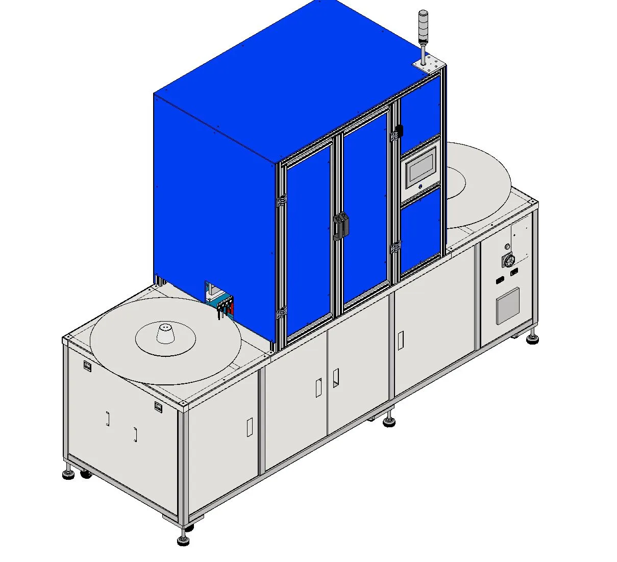
Motionwell Automation designed and built a tray-fed filling and sealing machine for a pharmaceutical customer in Singapore, installed in their cleanroom. It fills small containers from three dosing heads and heat-seals them on the same machine, so no open container is handled between dosing and closing. Containers arrive on a turning tray at one end, pass through the dosing and sealing stations on a linear transport, and leave on a second turning tray at the other end.
The machine is the delivered build behind our filling machines capability page, and it is worth being precise about what it is. It is a small-volume dispensing and sealing cell, built from an industrial dispensing system and not from bottling-line components. Drum, pail and IBC work is a different class of equipment and is covered under bulk filling machines.
How Is the Tray-fed Platform Laid Out, Station by Station?
Reading the machine in order of travel explains most of the design choices.
| Station | What happens | Why it is built that way |
|---|---|---|
| Infeed turning tray | Empty containers are loaded in a machined tray on a rotating plate | The tray locates the container, so a new container format is a tray set machined locally |
| Pick and transfer | A pneumatic gripper lifts containers from the tray and sets them on the transport | A parallel gripper working a fixed stroke between hard stops repeats mechanically, so there is no taught position to drift and nothing to re-qualify after a power cycle |
| Dosing | Three diaphragm dispense valves fill three containers per cycle | A diaphragm keeps the product off the valve actuator and holds the wetted path to a handful of parts that come off in minutes, which is what a cleanroom cleaning routine has to live with |
| Presence check | Fibre-optic sensors confirm a container is in position before a valve opens or the sealing tooling comes down | Sensed, because a timer cannot tell a missing container from a late one, and a valve opening over an empty tray pocket puts product on the tray |
| Heat sealing | Cartridge-heated sealing tooling closes the container under temperature control | Closed-loop control on a calibrated Type K thermocouple, because seal strength follows temperature and a thermostat’s swing shows up as a weak seal that looks fine |
| Outfeed turning tray | Sealed containers are set back into a tray on the second rotating plate | The same tray set as the infeed, so one change part covers both ends of the machine |
The infeed turntable presents containers to the machine, while the outfeed turntable receives sealed containers. Tray capacity, replenishment and unloading time are included in the sustained-rate calculation. Acceptance testing covers complete loading and unloading cycles as well as the dosing operation.
Station motion is pneumatic throughout: compact cylinders and mini slides for the short strokes, parallel grippers at the transfer, and filtered, regulated air preparation behind them. Every move is a fixed stroke between two hard stops, so repeatability comes from the mechanics, and there are no servo axes to tune or qualify inside the cleanroom. The actuators are catalogue items, which matters only after handover: a cylinder or slide with a distributor behind it is replaced within a shift, while a bespoke actuator puts the machine back on somebody else’s drawing and lead time.
How Do the Three Dosing Heads Meter the Fill?
Each head is a diaphragm dispense valve. Product sits in a pressure-regulated fluid tank, passes through a liquid manifold that splits it to the three valves, and leaves through a dispensing tip of a chosen gauge. The valve opens for a set time against that regulated pressure, and the volume that passes in that time is the dose. A float switch in the tank warns before the supply runs low.
That is a time and pressure method. It is neither positive displacement nor weighing, and the choice is deliberate: the wetted path is a tank, tubing, a manifold, a diaphragm and a tip, with no piston, cylinder or check valve to strip and clean, and the diaphragm keeps the product away from the valve actuator entirely. Three containers fill on every cycle, and both the volume range and the tolerance band follow from the tip gauge, the tank pressure and the product itself, never from the machine alone.
| What sets the dose | Where it is controlled | What upsets it |
|---|---|---|
| Fluid pressure | Regulator on the fluid tank | Tank level falling, air supply drift |
| Valve open time | Recipe setting on the HMI | Nothing once set; this is the stable variable |
| Tip gauge | Interchangeable dispensing tips | A worn or partly blocked tip |
| Product viscosity | Not on the machine | Product temperature, batch-to-batch variation |
The last row is the one to read twice. A time and pressure filler is only as repeatable as the product it is fed. A liquid that thickens with a few degrees of room temperature change will drift inside the tolerance band before anything on the machine has changed. Where a specification calls for a tighter band than time and pressure dosing will hold on the product, or the product is viscous or carries particulates, the answer is a different dosing technology, and the reasoning is set out on our volumetric versus gravimetric filling page.
Because the diaphragm closes directly behind the tip, very little product sits between the shut-off point and the tip outlet, which is what keeps stringing and drips manageable at small doses without a separate cut-off mechanism.
How Does the Heat-sealing Station Hold Its Temperature?
The sealing station is built around cartridge heaters set into machined heater plates and blocks, with heat isolator blocks between the hot tooling and the frame so the heat stays where the seal is made. Type K thermocouples read the tooling temperature and a dedicated closed-loop temperature controller holds the set point through a solid state relay. The relay is solid state and not a contactor, because the loop switches the heaters continuously, and at that duty a mechanical contactor becomes a consumable whose failure presents as a sealing defect long before it presents as an electrical fault. The thermocouples were calibrated by an external metrology lab, so the temperature shown on the HMI can be traced.
Seal strength depends on tooling temperature, contact dwell and applied force. The temperature controller holds the setpoint against the calibrated sensor. The control sequence sets dwell, while regulated air pressure and cylinder geometry determine the available sealing force; flow controls adjust approach and return speed. The recipe and verification method are established for the closure. Screw and crimp closures have their own tooling options on our capping and sealing systems page.
What Materials, Guarding and Environment Is It Built For?
| Parameter | Specification |
|---|---|
| Dosing heads | Three, filling three containers per cycle |
| Fill volume | Small-volume dosing; the range follows from the dispensing tip gauge and the tank pressure set for the product |
| Filling accuracy | A tolerance band agreed per product, then verified on the intended head at acceptance testing |
| Throughput | Set by fill volume and seal dwell time, established on the customer container |
| Dosing method | Time and pressure through Nordson diaphragm dispense valves |
| Sealing | Heat seal, closed-loop temperature control |
| Container feed | Continuous dual turning-tray feed, trays machined locally |
| Product-contact material | Stainless steel; grade and surface finish fixed at design review against the product chemistry and the cleaning agents |
| Guarding | Stainless steel cabinet, aluminium profile guard with clear polycarbonate panels |
| Environment | Designed for ISO Class 7 and Class 8 cleanrooms |
| Control | PLC and HMI, tower light, emergency stop, rotary electrical isolator |
| Footprint | Single-bay frame with a turntable at each end, dimensions fixed at layout review |
The cabinet and frame are stainless steel, with an aluminium-profile guard and clear polycarbonate panels around the working area. Product-contact material grade and surface finish are selected against the product chemistry and cleaning agents at design review. The exterior is cleaned by wipe-down, and removable wetted parts follow the agreed dismantling and cleaning procedure. Our cleanroom automation equipment page explains material, access and particle-control choices for installation in classified production areas.
The completed machine was put through low-voltage directive electrical safety testing by an external test house, with test reports.
How Is a Change of Container Format Handled?
The tray is the change part. A different container needs a different tray set, machined to suit, so a format change is a tray swap. The trays, turning trays and tray spacers on this build were machined by local workshops in Singapore, which is what keeps a new tray set a short lead item.
Fill volume is a recipe setting across the range that one tip gauge and one tank pressure cover, because the dose is a valve open time against a regulated pressure. Outside that range, or for a product that behaves differently at the tip, the change is a different tip gauge or a different dosing head. How changeover time is engineered on a filling line, and why it decides daily output more than rated speed does, is set out on our filling line changeover page.
What Documentation and Validation Support Comes with a Machine Like This?
For pharmaceutical customers, Motionwell can supply IQ/OQ/PQ documentation with a machine of this class, run factory acceptance testing at our Singapore facility before shipment, and support site acceptance testing in the customer’s cleanroom. The scope is agreed at enquiry stage, because the document set shapes the test plan and the calibration evidence that has to be collected during the build. On this machine that evidence included external calibration of the sealing thermocouples and the electrical safety test report.
Where the control system itself falls in scope, that work is handled as computer system validation, and the batch record side can be handled through an electronic batch record system. Neither is bundled by default; both are available.
Which Five Decisions Shaped This Machine, and What Did Each Cost?
Time and pressure dosing. A positive displacement pump would hold a tighter band and would care less about viscosity. It was not the right answer here because the doses are small, the valve type suits low to medium viscosity liquids, and every wetted precision part is a part that has to be stripped, cleaned and inspected in a cleanroom. Diaphragm valves fed from a pressure tank keep the wetted path to a handful of parts that come off in minutes. The cost is that the fill is only as stable as the fluid pressure and the product, so the tolerance band is a promise about the machine and the product together, never about the machine on its own.
Three heads on a linear transport. A carousel with more heads runs faster, and it pays for the speed with format range: star wheels and container guides are cut around one container envelope. This machine gives that speed up and keeps the container located in a tray pocket from infeed to outfeed, so the tray is the only part that changes with the container. For small containers that would tip on a conveyor, that is the better trade.
Pneumatic stations. Every motion on the machine is a cylinder or slide between hard stops. That gives fewer drives to maintain, no axis calibration to record, and simpler qualification. What it gives up is flexibility: a new stroke length is a mechanical change. On a machine where the container format is fixed for long runs and changed as a tray set, that is a price worth paying.
Heat sealing. A heat seal needs a temperature loop, a calibrated sensor and dwell time per container, which is where the upper end of the cycle time comes from. It was chosen because the closure on this product is heat-sealed. Where the closure is a cap, the sealing station is a different design, and our vial capping and uncapping unit was built as a separate project for that reason.
Cleaning access built into the layout. The exterior supports wipe-down cleaning, while the wetted path comes apart for cleaning and inspection. Tank, manifold, valve and tip access are reviewed together so the cleaning procedure can be performed around the installed machine.
Where Else Does This Engineering Show Up?
This project sits within Motionwell’s work for the pharmaceutical and packaging industry, with related builds for medical device manufacturers where contact-surface materials and cleanroom construction drive the specification. Cleanroom construction detail is covered in the cleanroom automation guide.
If you are specifying a filling machine, send us the product viscosity, fill range, container format and target rate and we will tell you which dosing method fits before anyone draws anything.