
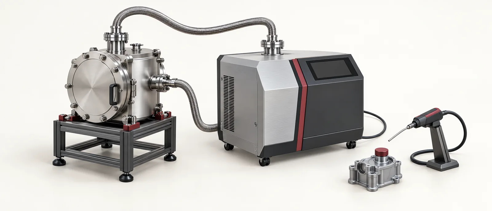
Conceptual equipment illustration.
Helium leak testing uses helium as a tracer gas and detects its passage through a leak. The test arrangement determines whether the result represents an overall leak rate, a local leak indication or another defined measurement. Select that arrangement from the component and acceptance requirement.
Start with the required leak rate, units, test pressure and tracer-gas concentration. A detector’s smallest advertised signal is not the same as the sensitivity of a complete production station.
Choose the Method Around the Component
| Method | Typical arrangement | Main design question |
|---|---|---|
| Vacuum chamber test | Tracer-filled component inside an evacuated chamber | Can the chamber and gas path provide the required response within the cycle? |
| Sniffer test | Probe samples near a component containing tracer gas | Can every required leak location be approached consistently? |
| Accumulation test | Escaping tracer builds up in a defined surrounding volume | Are volume, mixing and measurement time controlled? |
INFICON’s tracer-gas methods overview illustrates these arrangements.
The wider leak-testing systems guide compares the application questions around leak testing. Helium testing should be chosen for a defined measurement need, not treated as an automatic replacement for every pressure-based method.
Check the Whole Gas Path
The fixture connection, valves, chamber, pumping arrangement and detector form a measurement system. A leak near the detector can produce a different response time from a leak on the actual component.
INFICON’s calibration guidance explains how reference-leak placement and background conditions affect the result. Verify the production gas path with an appropriate reference arrangement as well as checking the detector itself.
For a chamber system, separate fixture or chamber leakage from component leakage during development. For a sniffer system, define probe path, approach and movement consistently enough to test the required locations.
Control Background and Recovery
Helium released during handling can raise the local background. A significant leak can also affect the conditions for the next test. Record background behaviour during repeated production cycles, not only on the first clean setup.
Define how the station checks that it is ready for the next part. An invalid or unstable measurement should remain distinguishable from a part that meets the limit. Include the recovery time after a gross leak in the capacity trial.
For packages and closures, the capping and sealing process defines the joint being assessed. Test conditions should correspond to the package requirement and its ability to tolerate the selected pressure or vacuum arrangement.
Document the Complete Cycle
Show loading, sealing to the fixture, gas preparation, measurement, recovery and unloading. Identify the valve states and permissions needed for each step. Associate the result with the component and test recipe.
An automated test equipment project should include reference checks, failed-part routing and interrupted-cycle handling. A laboratory development sequence can provide the starting evidence, while laboratory automation can help repeat the test and preserve results.
Acceptance Evidence to Retain
Use a suitable calibrated reference leak or reference assembly, known acceptable components and the relevant fault conditions. Record units, concentration, pressure, background, measurement time and result. Check the required response through the actual station plumbing.
Do not substitute a roughly drilled hole for a quantified reference leak. The acceptance record should demonstrate that the system detects the specified condition, including after normal handling and recovery events.