
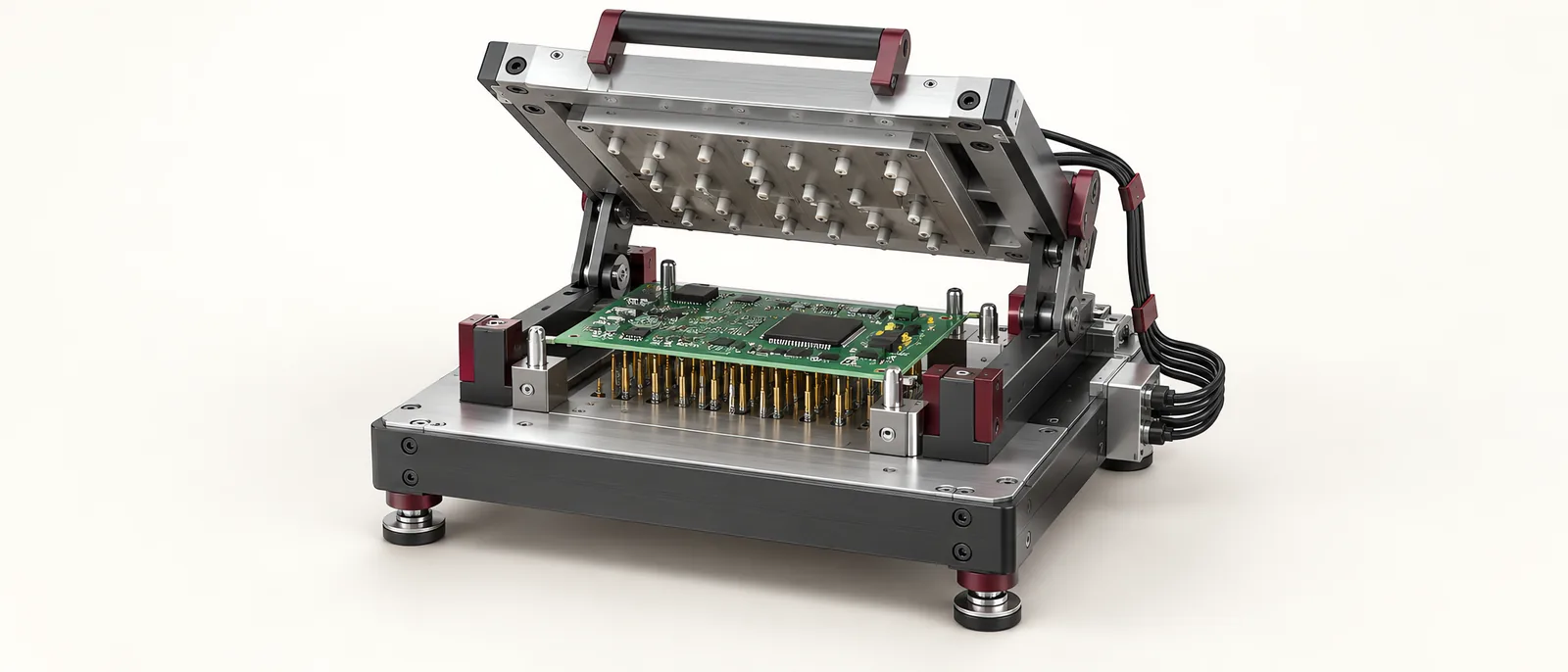
Conceptual equipment illustration.
A functional test fixture holds a device under test in a repeatable position and connects it to the power, signals and instruments needed to check its behaviour. Its design should make a product failure distinguishable from a poor contact, incorrect connection or worn locating feature.
For a PCB assembly, a bed-of-nails arrangement is one possible contact method. The fixture structure does not determine whether the test is functional or in-circuit; the measurement sequence does. Define that sequence before selecting probes and designing the nest.
Make the Contact Map the Starting Document
Give each test point a stable identity. Record the signal, its electrical requirements, the physical contact location and the instrument channel at the other end. Add the expected product state when the connection is used: powered, unpowered, programmed or running a particular function.
This document ties the fixture to the automated test equipment around it. It should remain understandable after a probe plate, cable or instrument has been replaced.
| Interface item | Design question | Acceptance evidence |
|---|---|---|
| Locating features | Which product surfaces establish position? | Repeated loading returns contacts to the intended pads |
| Probe travel | What compression is reached when the fixture closes? | Probes operate within their specified working travel |
| Board support | Where does the closing force enter the assembly? | Support limits board deflection without loading sensitive components |
| Power and signals | What current, voltage and signal behaviour must pass? | Measurements remain valid through the complete contact path |
| External connections | How are cables identified and restrained? | Connections can be inspected and restored from documentation |
A good location strategy uses product features whose tolerances are known. Solder joints and flexible connectors make poor accidental datums. Include component clearances in the mechanical fixture review so a pressure plate cannot land on a newly taller component after a board revision.
Separate Contact Reliability From Product Performance
Before powering the DUT, use the appropriate connection checks for the test architecture. During development, record raw readings alongside the pass/fail decision. If several unrelated measurements change when the fixture is reopened and closed, investigate contact and seating before changing product limits.
Probe selection should reflect the pad surface, available spacing, electrical duty and working travel. A tip that works on one surface may damage another. Use the probe manufacturer’s specifications for the selected part and include probe replacement access in the design.
Run a controlled comparison with the same reference device, repeated fixture loading and a second known device. This helps separate loading variation from genuine unit-to-unit variation. A reference device is also a maintained asset: record its identity and verification history, so a damaged reference does not become the acceptance standard.
Choose a Signal Route You Can Maintain
The FixturFab signal-interface guide describes hand-wired receptacles and PCB-based routing to instrumentation. Both are practical architectures. Compare them against the electrical requirements, fixture quantity and expected revisions instead of assuming a universal crossover at a particular number of test points.
For a wire harness, document both ends and provide access for continuity checks. For a routing PCB, retain the design revision and connector pinout. In either arrangement, consider cable movement, shielding, grounding and separation between sensitive measurements and switched loads.
The same maintainability concern appears in electronics automation: a station should be recoverable when the person who originally wired it is unavailable.
Build the Acceptance Test Around Real Changes
Start with a correctly assembled fixture and then check the conditions it will encounter during maintenance and production:
- Reload the DUT through multiple fixture cycles and compare the relevant raw measurements.
- Introduce agreed known defects or test artefacts and confirm that the intended test detects them.
- Replace a wear component, such as a probe or locating insert, and repeat the fixture verification.
- Disconnect a required signal and confirm that an incomplete test cannot return a product pass.
- Select a different fixture or product revision and check that the matching software configuration is required.
Keep the fixture revision, test software version and instrument configuration with the results. The cleanroom ATE case study shows the broader machine context in which loading, test execution and records must agree.
Need a fixture or automated test station? Discuss the test with Motionwell. A board drawing or existing test sequence can help identify the mechanical and electrical interfaces.