
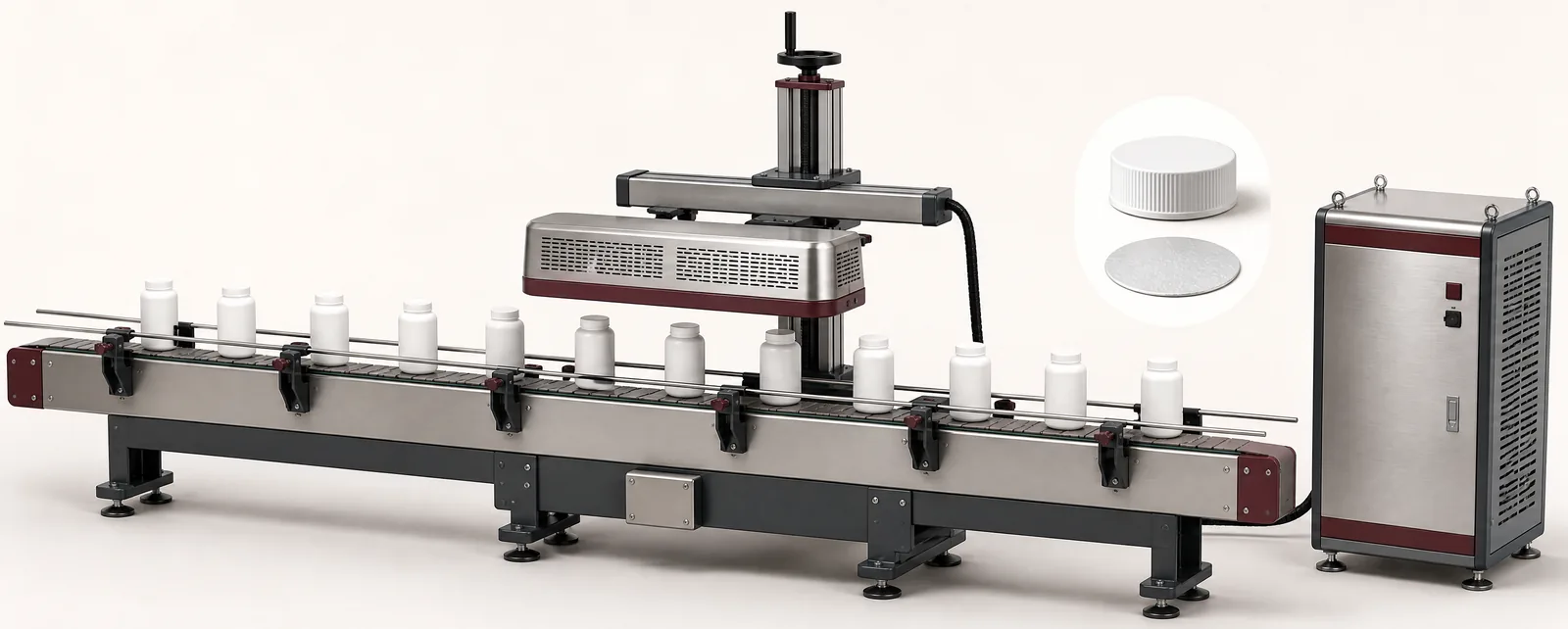
Conceptual equipment illustration.
An induction sealing machine heats a compatible foil liner through an electromagnetic field so that its sealing layer can bond to the container rim. Consistent sealing depends on the container, liner and closure as well as the power setting and conveyor speed.
Start by confirming the packaging combination. A different bottle resin, rim condition or liner construction can change the process even when the cap diameter remains the same.
Establish Contact Before Adding Heat
The liner needs the intended contact with the sealing surface. Review the closure application and the condition of the container rim. Product on the rim, a damaged sealing land or inconsistent cap application can create a problem that a higher power setting does not resolve.
Enercon’s induction-sealing guidance identifies application torque as an important contributor to liner contact. Set it for the actual container and closure system, then verify it through the packaging trial.
The upstream capping and sealing arrangement should therefore be included when diagnosing inconsistent induction seals.
Control the Heating Window
Three variables deserve separate attention: field strength, liner position in the field and exposure time. Power influences the field; head alignment and height influence how the liner passes through it; conveyor speed influences exposure time.
Enercon’s explanation of the induction field describes these relationships. Excessive heating can damage a liner, while insufficient heating can leave an incomplete bond. The useful operating range should be established with the selected packaging components.
Do not compare two trials by the displayed power percentage alone if the head position, speed or packaging has also changed. Record the complete setup.
A Fault-Isolation Sequence
| Observed result | Check before adjusting the process |
|---|---|
| Local unsealed area | Rim cleanliness, damage, liner contact and head alignment |
| Broadly weak bond | Liner compatibility and the established heating window |
| Burnt or distorted liner | Exposure conditions and the actual power/speed combination |
| Intermittent failures after capping | Closure application consistency and component variation |
| Failures around a line stop | Product position under the head and stop/restart sequence |
Use matched samples to isolate the cause. Change one variable at a time and inspect the full seal circumference after the specified cooling condition. A visually complete ring may still need a functional test to demonstrate the required seal performance.
Include Stop and Restart Behaviour
A stopped conveyor can leave packages in a different exposure condition from normal production. Define how the sealer and conveyor coordinate, what happens to packages already beneath the head and how affected packages are identified.
Also define the response to a missing cap or liner, where detection is included. A sealer-running signal does not prove that each container has a suitable closure.
These interfaces belong in the packaging-line integration plan, especially when the filler, capper and sealer come from different suppliers.
Verify the Seal You Actually Need
Agree the inspection method, sample conditioning and required result. Depending on the product, this may include visual examination, peel behaviour or a defined integrity test. The leak-testing systems guide explains why the test method must match the package and defect being assessed.
Retain the container, cap and liner specifications with the proven process settings. Repeat the relevant checks when a packaging component changes.
For a complete filling-machine system, consider induction sealing as a coordinated downstream process, not a standalone power box. Discuss your filling and sealing line with Motionwell.