
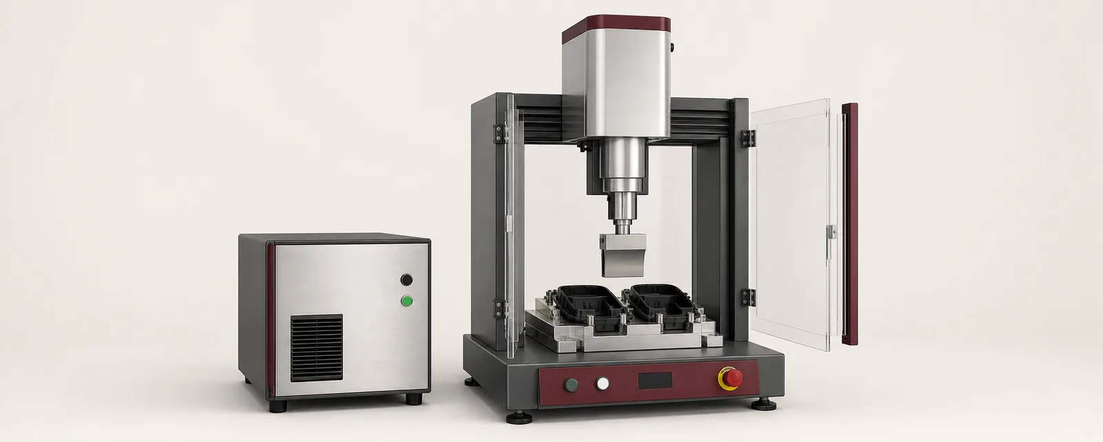
Conceptual equipment illustration.
An ultrasonic welding machine for plastics combines a power supply, an acoustic stack, an actuator and a fixture that supports the workpiece. Selecting the machine starts with the joint and material. Generator power or nominal frequency alone cannot establish whether the assembly will weld consistently.
The equipment must deliver vibration to the intended interface while holding the components in a repeatable position. That is a different task from selecting a metal-welding system, even though both processes can use ultrasonics.
Follow the Energy Path
The power supply drives a converter that produces mechanical vibration. The acoustic tooling transfers that motion to the part. At the designed joint, local heating allows suitable thermoplastic surfaces to fuse; the assembly is then held while the joint stabilises.
Branson’s ultrasonic plastics overview describes the process and shows separate actuator and power-supply options. Treat the selected components as a matched system. A different horn or part geometry can change the acoustic behaviour even when the generator remains the same.
What to Review in a Machine Proposal
| Item | Evidence to request from the trial |
|---|---|
| Horn contact | Repeatable contact without unacceptable surface marking |
| Fixture support | Joint alignment maintained throughout the weld and hold stages |
| Actuator | Controlled approach and the required process force or motion profile |
| Acoustic arrangement | Compatibility with the component geometry and selected operating frequency |
| Process control | A mode and limits that distinguish the relevant good and bad cycles |
| Data interface | Result and recipe identity available to the machine controller |
Frequency selection belongs to the application and tooling design. Avoid assuming that a higher frequency is always more precise or that greater generator power can correct an unsuitable joint.
Choose a Control Mode That Matches the Process
Depending on the equipment, the weld can be controlled using time, energy, distance or other available process parameters. A mode name does not by itself define the finished-joint requirement.
For example, reaching an energy target confirms that the control criterion was reached. It does not directly measure leak tightness or retention strength. Use trial assemblies to establish the relationship between process records and the product tests that matter.
In a medical-device assembly machine, preserve the association between the component, recipe, cycle result and any subsequent inspection. Keep aborted cycles distinguishable from completed cycles that fail a product test.
Integrate Loading and Recovery
Show how parts enter the nest, how orientation is checked and when the actuator receives permission to start. Include the horn clearance needed for tooling changes and servicing.
A rotary indexing assembly machine must wait for the welding station to reach a suitable state before indexing. The controls should also describe the destination of a part after an interrupted weld. Repeating the cycle automatically may alter a partially formed joint.
For container or closure work, compare the joining requirement with the capping and sealing process. The correct equipment depends on the materials and joint design, not simply the need to close a package.
Keep a Process Development Record
Run representative moulding variations and retain samples across the selected operating range. Record the material, joint revision, horn and fixture identities, settings and inspection results. Include cosmetic appearance and critical dimensions alongside strength or sealing tests.
Repeat the setup after a tooling change. If the process depends on a delicate manual adjustment, identify how production will reproduce and verify it. This is often more useful than collecting a large number of cycles at one carefully tuned setting.
Motionwell can discuss how the chosen process fits into custom automation equipment. Contact us about your plastics assembly.