
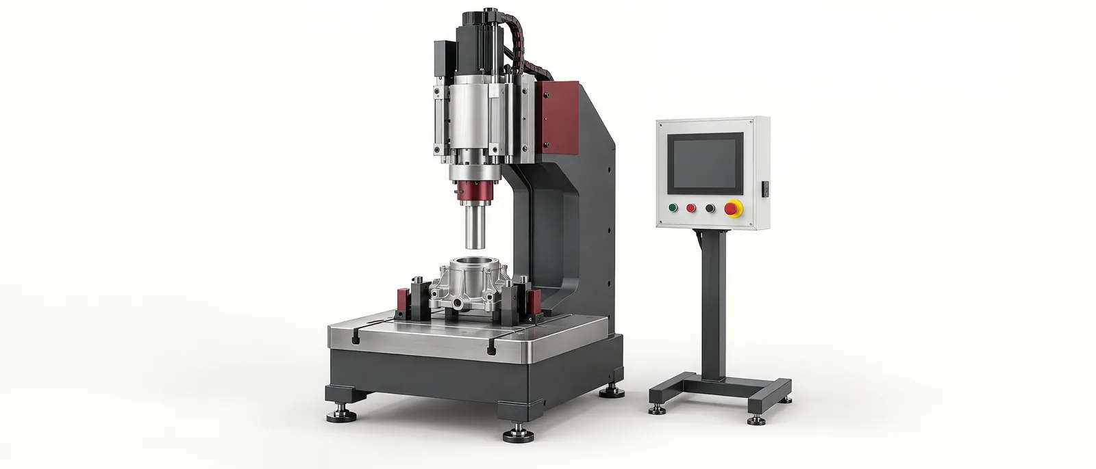
Conceptual equipment illustration.
A press fit machine must apply the required joining force while keeping the two components aligned and measuring the process at a meaningful location. Maximum force alone does not define the machine. Usable stroke, working height, frame stiffness and fixture access can determine whether the proposed press suits the assembly.
Start with the joined components, their locating surfaces and the expected insertion direction. For custom automation solutions, this process definition should precede the choice of a standalone press, an automated station or a press module inside a larger machine.
Define the Working Envelope
Separate approach travel, joining travel and clearance for loading. A press with adequate stroke may still leave insufficient space for the fixture and a tall component. Check the tooling-change position as well as the production position.
Draw the complete force path from the ram through the tool, part, nest and machine frame. Off-centre loading or an unsupported part wall can cause movement that appears in the process result. Review guides and locating features before attempting to correct an alignment problem through control settings.
For a bearing insertion, for example, the support should act through the intended assembly surfaces. A trial should reveal whether the fixture loads an unintended feature or permits the component to tilt at the start of insertion. The exact support arrangement follows the component design.
Compare What the Sensors Actually Measure
Kistler’s electromechanical joining systems illustrate integrated force-displacement monitoring and cycle documentation. When evaluating any proposed system, ask where each quantity is measured and how it relates to the joint.
| Quantity | Question to resolve |
|---|---|
| Force | Is the measurement in the joining load path, and is its range appropriate? |
| Displacement | Does it represent ram movement or a measurement closer to the component? |
| Position reference | Is the cycle referenced to the machine, tool or detected part contact? |
| Result association | How is the curve linked to the correct assembly and recipe? |
Ram movement can include fixture or frame deflection. If the assembly requires a final component dimension, decide whether an additional dimensional check is needed. A good-looking force curve and a correct finished dimension are related evidence, not interchangeable measurements.
Establish Process Limits From Real Parts
Capture curves from representative acceptable assemblies and known process faults. Examine the entry, insertion and final-seating regions separately. Include missing components, incorrect orientation or the relevant fit variations in a controlled trial.
The rotary indexing assembly guide explains how a monitored joining operation fits into a multi-station sequence. For a dedicated press purchase, also verify the response after a failed cycle: the machine must retain the result and route the assembly appropriately.
Make Tool Changes Repeatable
Specify locating datums for interchangeable nests and punches. Give each tooling set an identity and associate it with the correct process recipe. After a change, check the working reference and first-piece result before normal production resumes.
A medical-device assembly machine may combine pressing with inspection and traceability. Separate those station results so that a later check can identify the operation that failed.
If the joint needs later disassembly or a different retention method, compare the product requirements with screwdriving and fastening systems. The choice of joining method should be resolved before fixing the press layout.
Acceptance Should Include the Difficult Cycle
Run the lowest and highest expected joining loads, the least favourable permitted alignment and a full tooling change. Check the resulting dimensions or retention characteristics against the product requirement. Include an interrupted cycle and a rejected assembly in the controls test.
That record gives production a usable baseline for the machine, tooling and process together. Discuss your press-fit assembly with Motionwell.