
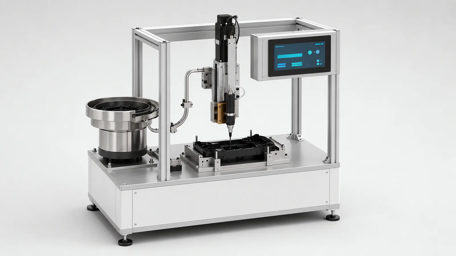
Motionwell builds automated screwdriving and fastening stations in Singapore, combining screw presentation, part location, controlled driver motion and per-fastener results. On our SCARA sensor panel assembly system, electric screwdrivers fasten modules to the panel substrate with recipe-selected torque targets and PLC result tracking. The fixture and driver support carry the thrust and reaction torque so the fastener enters the joint squarely.
Screwdriver spindles, torque controllers, screw presenters and robot arms come in as catalogue items, and what we design is the station around them: how the part is held against the reaction torque, how a screw arrives at the bit, how the driver is positioned and pressed, what the machine does with a fastener it could not complete, and what ends up in the record. Fastening has shipped here as a station inside a machine, and the delivered work is single-spindle electric driving on assembly lines, plus torque-controlled nutrunners carried on a robot flange removing fasteners on a battery dismantling line, where the nutrunner is selected for the reaction it puts back into the arm, because an arm absorbing the reaction of a seized fastener loses position before the fastener moves. The hardest version of this work we have delivered is unbolting, on the EV battery teardown line.
One boundary first, because the two get filed together: this page is about a fastener that clamps a joint. Closing a container is a different machine with different physics, covered on our capping and sealing systems page. The line behind most of what follows is documented in the SCARA panel assembly case study.
Why Is a Screw a Process and Not an Operation?
What you actually care about is the clamp load holding the joint together, and nothing on the station measures clamp load directly.
Torque measures the resistance to turning. Most of that resistance is friction, under the head and in the threads. So the relationship between the number the driver reads and the load in the joint is set by the friction of the day: a different plating batch, a thread-locking patch, a trace of oil, swarf trapped under the head, a boss moulded slightly differently from last month. Any of those changes the clamp load while the recorded torque stays exactly where the recipe put it. That is why a fastener is instrumented, and it is what separates a robotic fastening system from a powered driver on a slide: the driver produces a torque, the system produces a decision and a record for each joint.
Read as a process, a fastening station owes four things per fastener. A target window. A signal watched through the whole event. A decision taken at the station that made the joint, while the unit is still there. And a record bound to the unit. The same discipline applies wherever a tool on a machine does work as well as holding a part. On a multi-station rotary assembly machine, a 12-station dial for example, we would put a load cell on every press station and record the full force-displacement curve against the part identity, so an out-of-band assembly is rejected at the station that caused it. That argument is worked through on the medical device assembly machine page and in how we design multi-station rotary assembly machines; on a threaded joint the second signal is cheaper, because the angle is already in the encoder.
What Do Torque and Angle Together Catch That Torque Alone Misses?
A correct drive has a shape. Near-zero torque while the screw runs down the thread, a snug point where the head touches the surface, then a rise as the joint compresses, then cutoff. Angle counted from the snug point is the signal that tracks how far the fastener actually turned while under load, so the acceptance criterion becomes a two-dimensional window: torque inside its band and angle inside its band. The combination is what classifies a failure, because each of the two signals alone lets a different class through.
| Failure signature | What happened at the joint | Torque and angle reading | What has to catch it |
|---|---|---|---|
| Cross-thread | The screw entered off-axis and cut across the existing thread on the first turn | Torque rises within a turn or two with no run-down phase, and target is reached far short of the angle band | The angle floor. The hole normally needs attention before another fastener goes in |
| Stripped thread or boss | The female thread failed, so the fastener turns without gaining load | Torque never reaches target inside the angle ceiling, or reaches it and collapses | The angle ceiling |
| Missing screw | Feeder starved, screw lost in the delivery tube, or the pick-up did not take one | The spindle runs to the angle ceiling at near-zero torque | A screw-present check at the nose, which stops the cycle before the driver commits |
| Screw not seated | The fastener tightened against something that should not be in the joint, or against a part standing proud on its boss | Both signals can land inside their bands, because the fastener genuinely was tightened | Depth at cutoff, or a head-height measurement downstream |
| Reached torque early on a burr | The driver met resistance that was not the joint, so cutoff fired before the head touched down | Torque correct, angle short of the band | The angle floor. Torque alone passes this one |
The fourth row is the limit of the method, and it is worth designing against. Torque and angle describe what the fastener did; they say nothing about where the head finished. Where the joint has a gasket, a stack of parts or a trapped-component risk, the check is the final Z position of the feed axis at cutoff, compared against the expected depth for that fastener. On a servo feed axis that is a free measurement already in the controller, and where the geometry is visible it can also be taken downstream as a height reading, described on our inline dimensional measurement page.
One point of comparison from the closure side of the same building. Where a torque record has to be kept on a screw closure, the capping head is specified servo-driven so the controller reads the whole application curve, as set out on our capping and sealing systems page. On a threaded fastener the angle summarises that curve in one number, which is why torque and angle per fastener is the practical specification, and storing a full curve per fastener is a data volume question worth asking early.
Why Does the Screw Feeder Decide More Than the Driver Does?
The driver is a bought instrument with a datasheet, while the feeder is a mechanism tuned to one screw and the part of the station that has to meet every fastener individually. A feed chain has the same stages whatever the fastener: a hopper holding a shift’s worth, a sorter with a tuned track and escapement returning wrongly oriented screws to the bowl, a delivery stage, and a presentation point where the bit takes one screw.
Two delivery families are worth understanding before a station is drawn, because they impose different conditions on the fastener itself.
| Blow feed | Pick-up, vacuum or magnetic | |
|---|---|---|
| How the screw reaches the bit | Escaped one at a time and blown along a tube to a nose jaw at the driver | The driver travels to a presenter, takes the screw on a magnetised bit or a vacuum sleeve, then moves to the hole |
| What it demands of the screw | A head-to-shank ratio and a length-to-diameter ratio the tube will carry head-first without tumbling, heads that do not interlock, no burrs or shed patch flakes | A ferrous shank for a magnetic bit, or a flat enough head face for a sleeve to seal against |
| Cycle cost | The screw travels while the driver is still working the previous joint | An extra trip to the presenter inside every fastener cycle |
| Access at the joint | The nose jaw needs clearance around and above the hole | Only the bit and sleeve enter the joint, so tight pockets stay reachable |
| Where it fails | Very short screws that tumble in the tube, very long ones that jam on a bend, flanged or headless fasteners, screws with washers that separate | Non-ferrous fasteners with no sealing face, and rate, because the trip is serial |
| Wear items | Tube bore, escapement, nose jaws | Sleeve, bit magnetisation, presenter track |
Both families demand the same thing above everything else: consistent screws. A batch with burrs on the head, plating flakes, mixed lengths or shedding thread-lock will jam either mechanism, and it fails intermittently, which is the expensive way to fail. The cost of feeding is chronically under-scoped in quotations generally: it is engineered against your screw, and a feeder that presents a wrong-way part every fiftieth cycle costs far more than it looks like it should, because every one of those is either a jam or a reject.
We have built escapement feeding stations on assembly machines, and bowl feeder retooling with starwheel indexing is work we take on for high-mix production. A screw presenter, though, is specified against a fastener, which is why the useful thing to send with an enquiry is a bag of the actual production screws, from the supplier you will buy from.
Is the Driver Bit a Consumable, and Who Is Costing It?
It is, and it carries a maintenance interval that rarely appears in a quotation. The bit transmits the whole applied torque through a small recess in the fastener head, so it is a heavily loaded interface and it wears in service. Wear rounds the driving faces, rounding increases cam-out, and cam-out damages the next recess as well as the bit.
Recess geometry sets how hard the bit has to work. A cruciform recess unloads the bit axially as torque rises, so it depends on thrust to stay engaged; a lobular or hex recess transmits torque without pushing the bit out of the head. That makes thrust part of the specification. Too little and the bit cams out of a recess that was fine; too much and an unsupported part deflects under the driver, moving the seating point the torque window was established against. This is one reason a SCARA suits fastening work: horizontal loads are carried by the two rotary joints while the vertical axis deals only with gravity and the driving load, so the arm is stiff in Z where screwdriving loads it, as set out on our robot integration services page.
The wear list for a fastening station is short and every item on it has an interval: bits, nose jaws or the pick-up sleeve, the delivery tube, the escapement, the feeder track, and the calibration of the torque measurement, which is a measuring instrument carrying a certificate. The value of a soak test before shipment is that it turns each of those into a number the maintenance schedule can carry.
One diagnostic is worth setting up at commissioning. A bit that is rounding shows in the data before it shows in the reject bin: at a fixed target torque the recorded angle drifts and the scatter inside the window widens, well before a fastener falls outside it. Trend the logged population, which costs nothing beyond a query on data the machine already keeps.
Can a Machine Fix a Joint That Was Not Designed to Be Automated?
No, and that is worth settling before a layout exists.
A person fastening by hand runs a control loop that nobody writes down. They feel the point drop into the thread, feel it bite, notice when it does not, back it off and start again. A station has none of that unless somebody paid for it, so the joint has to supply what the hand was quietly supplying.
| Joint feature | What the station needs from it | What happens without it |
|---|---|---|
| Lead-in at the hole | A chamfer or counterbore giving the point a target inside the position tolerance | A cross-thread rate that no torque setting improves |
| Hole position and the tolerance stack | A taught position plus enough vision correction or compliance to absorb the residual | The thread starts off-axis, and the record fills with early-torque rejects |
| Clearance around and above the hole | Room for the nose jaw or sleeve and a straight approach for the bit | A joint a hand driver reaches and an automated nose cannot, found late |
| Support under the joint | A backing face so thrust does not deflect the part | The seating point moves with the deflection, so one window will not cover the whole part |
| Screw length against boss depth | A fastener that seats on its head | A bottoming screw produces a torque peak that reads as a good joint |
| Thread-forming into a moulded boss | A forming torque genuinely separable from the seating torque | The two overlap, so the usable window narrows to whatever moulding variation leaves |
| One fastener specification | Consistent coating, patch and supplier | Friction moves, so the same torque delivers a different clamp load and the window has to be re-established |
Every row on that list is a drawing change while the product is on a screen and a rebuild afterwards. Tooling is cut around a geometry, so a joint that moves after detail engineering has started takes the nests, the nose and the feeder track with it, and that is scrapped work. The practical request that follows: send production-representative parts, because a moulded boss and a machined hole form threads differently and only one of them tells you what the window will be.
Where the product uses an interference joint instead of a thread, a press fit machine needs a different load path and process record. Resolve the required retention and serviceability at the joint-design stage before selecting the fastening station.
A permanent riveted connection differs from a removable screw joint. orbital forming versus screw fastening covers the forming geometry and required finished-joint function.
What Has to Be in the Record for Every Fastener?
On a medical or automotive part the record is the deliverable, so it has to be specific enough that a question asked two years later lands on one joint of one unit.
A per-fastener row carries the unit identity, the fastener position, the recipe target and window in force at that moment, the final torque, the result, the timestamp, and the station and spindle that did the work. One item is easy to leave out: position. A record saying fastener three was out of window is only actionable if the record also fixes which hole fastener three is, and that mapping belongs in the recipe and on the drawing, because program order changes when somebody optimises the path.
The result is linked to the panel serial number and fastener position at the station. On the panel line, torque is the recorded fastening measurement. Where angle monitoring is specified, the selected controller and record structure also carry the angle result and acceptance window. Identity capture and data binding are explained on our code reading and traceability page.
Where the line is regulated the log stops being process data and becomes a record. A fastening record kept as evidence that a joint was made correctly falls under 21 CFR Part 11, which decides where it is stored, who may alter it and what audit trail follows it, and that split gets settled during validation. How it lands inside a batch or device history record is on our electronic batch record page. Where the requirement arrives as a customer specification, send us that specification: the window definition and the retention period live in it, and both change what the machine has to store.
What Happens to a Part When a Screw Fails?
A failed screw is not a paused cycle, and the reason is in the data. The acceptance window is built around a run-down phase followed by a rise. Drive again into a fastener that is already part-tightened and there is no run-down: torque arrives almost instantly and the angle carries no information at all. A re-drive therefore produces a number that would pass a torque-only check while proving nothing, which is precisely the outcome the station was bought to prevent.
The other half of it is mechanical. Some failures have already damaged the female thread. A stripped boss will not hold at any torque, and a cross-threaded hole needs re-cutting or the part goes. So the path has to be defined per failure class at concept stage, and written into the specification.
| Failure at the station | Can the machine retry? | Where the unit goes | What closes the record |
|---|---|---|---|
| Missing screw at a hole never touched | Yes, once, with a retry counter | Stays in the machine | The successful attempt plus the retry count, so a station drifting towards retries is visible |
| Torque low across the full angle band | No, the thread has already failed | Rework or scrap, by class | A manual disposition recorded against the unit |
| Early torque with short angle | Not without removing the fastener first | Rework station with a written procedure | Who removed it, what was done to the thread, and the result of the re-drive |
| Both signals in band, joint not closed | No, and it is usually detected downstream | Hold for review | The downstream measurement, linked to the same unit identity |
The physical side follows from that table. Destinations that differ by class need a robot pick-off placing units separately, because a single bin throws away the distinction the station just paid to make; where one destination is enough, the pattern is a pneumatic pusher into a quarantine bin downstream of the deciding station. Either way the reject device needs a sensor proving the unit actually left the line, since a stuck pusher passes failed product while the log still records a rejection. The same reasoning applied to inspection rejects is on our machine vision inspection page.
One rule holds the whole thing together. A unit that leaves for manual rework has to come back with a record saying what was done to it, or the traceability the station was built for ends at the station door and the evidence has a hole in it exactly where the failure was.
Where Does a Cobot Suit Screwdriving, and Where Does the Bit Rule Out an Open Cell?
The instrumentation transfers to a collaborative arm unchanged. The safety case does not, and the reason is the bit.
Pressure is force divided by contact area, so a protruding driver tip concentrates the whole contact force onto a very small patch and can fail a pressure limit at a force that passes with room to spare. The geometry a contact assessment treats most strictly compounds it: a hand held between a moving tool and a fixed surface cannot move away, and that is the posture a fastening station creates by construction, since the part is clamped on a fixture and the tool comes down onto it. Contact limits have to be verified by measurement on the built cell with the real tool and the real workpiece. ISO 10218-1 was revised in 2025, the third edition and the first substantive revision since 2011, and it adds end-effector guidance alongside robot classifications and cybersecurity requirements, with each safety function on the cell rated for performance level under ISO 13849-1.
That is a shape we build: fastening sits inside an otherwise collaborative cell with the driving station itself guarded, so the arm loads and unloads in the open and the bit never travels where a person stands. The wider assessment is on our collaborative robot applications page.
Where a collaborative arm genuinely earns its place on this work is low volume with a high mix and a person in the loop, because a reprogrammable device beats a faster one when the mix changes more often than the parts do. Where it does not is a fixed high-rate job on one part number with every hole on one face, which is SCARA territory: four axes are enough, the footprint is small, and the vertical axis is stiff where the driving load acts.
When Is an Automated Fastening Station the Wrong Buy?
Three situations send the answer somewhere else, and each one is cheaper to find before a layout exists.
Few fasteners, low volume, and no record to keep. A bench station with a torque-controlled hand driver, a fixture and a fastener count covers a great deal of assembly work perfectly well. The instrumentation is what you pay for on an automated station, and if nobody is going to retain the evidence you are buying the expensive half without using it.
The fastener list has nothing in common. Each screw family brings its own escapement, track, delivery bore, nose and bit. A station covering unlike fasteners is several stations sharing a cabinet, and it gets quoted and maintained as such whether or not it is drawn that way.
The joint cannot be reached by a nose. A hand driver reaches into pockets and behind ribs that an automated nose and tube cannot enter. The answer there is a part change or a retained manual operation.
Where a proven standard machine covers your joint at a lower price than anything we would build, that is the recommendation you get, and establishing it costs a conversation. On a station we do build, we build to a specification and support your conformity work, including LVD and CE testing and MOM lifting certification where the machine includes lifting equipment.
Which Questions Settle the Specification?
Run these in order. The first that gives a hard answer usually settles the architecture, and where two disagree the station has two jobs in it.
- What has to be proven about the joint: screws driven, or clamp load evidenced per fastener and retained? The answer sets the whole cost shape.
- What is the fastener, exactly? Thread, head, recess, drive length, coating, patch and supplier, all of them fixed.
- What is the female side: tapped metal, a thread-forming screw into a moulded boss, a nut or a rivet nut? It decides whether run-down separates from seating at all.
- How many fasteners per unit, and at what rate? This sets spindle count, and whether the driver travels to the holes or the part travels to the driver.
- Can every hole be reached in one attitude? A hole on a second face is a second station, a rotation or a wrist, and it is cheaper to find on a drawing.
- Who stands there, and how often? This decides the guarding before it decides the arm.
- Where does a failed unit go, and who closes its record? The answer designs the reject hardware and the rework procedure together.
| Your situation | Start from | Why |
|---|---|---|
| Few fasteners, low volume, no retained record | Bench station with a torque-controlled hand driver | The instrumentation is the cost, and you are not buying evidence |
| High rate, one part number, all holes on one face | Fixed spindle or a SCARA station with a travelling driver | Planar work at rate, with thrust taken on a stiff vertical axis |
| High mix, low volume, an operator in the loop | Collaborative arm loading, with the driving station guarded | Reprogrammable beats fast when the mix moves faster than the parts |
| Screws too short, too long or too flanged for a tube | Pick-up from a presenter | The tube sets the geometry it is able to carry |
| Regulated device, per-unit record retained | Torque and angle per fastener bound to the serial number at the station | The record is part of the product, and it cannot be added later |
| Fasteners being removed | Torque-controlled nutrunner with angle as a stop condition | A fastener that has not broken loose inside the expected angle is a stop, as on our battery module automation work |
| The joint has no lead-in and no support | A part change before a machine quotation | No torque setting substitutes for a chamfer |
Lead time runs 16 to 24 weeks from concept approval to factory acceptance testing on a standard build, and 24 to 32 weeks where cleanroom compatibility or full validation documentation applies. Design, fabrication, assembly and testing happen at Woodlands Link with an in-house design team of eight, which is why a Singapore buyer attends the factory acceptance test without flying to it. That matters more on fastening than on most stations, because the settings that decide whether it runs are found on your own screws and your own bosses.
Standards Used in Machine Design and Validation
These references inform the design, testing and documentation described on this page. Each row links to its primary source and records the edition checked.
| Standard | Current edition | What it means for your machine |
|---|---|---|
| ISO 10218-1: Robotics, safety requirements, Part 1: industrial robots | ISO 10218-1:2025 | Published February 2025, the third edition and the first substantive revision since 2011. It adds robot classifications with matching functional safety requirements and safety-related cybersecurity requirements. Most of ISO/TS 15066:2016 on collaborative operation moved into Part 2.Checked 12 Sep 2026 against ISO 10218-1:2025 (iso.org/standard/73933.html) |
| ISO 13849-1: Safety of machinery, safety-related parts of control systems | ISO 13849-1:2023 | Provides the design method for safety-related control functions, including architecture, component reliability, diagnostic coverage and common-cause failure measures. The machine risk assessment establishes the required Performance Level; design calculations and validation provide the evidence for each function.Checked 1 Sep 2026 against ISO 10218-1:2025 normative references |
Frequently Asked Questions
How many fasteners a minute can an automated station drive?
Ask for the number on your own part, because the driver is rarely what sets it. The station cycle is the move to the hole, the screw arriving at the bit, the run-down length of that particular screw, the tightening phase and the settle before cutoff, plus whatever the machine does with a fastener it could not complete. A driver datasheet quotes a free-running speed measured with nothing else happening, which is not a cycle time. We time the sequence on your fasteners and your bosses before quoting a rate, because a long thread engagement is a different cycle from a screw that seats almost as soon as it starts.
Can a fastening station be retrofitted to a machine we already run?
Often, and control system modernisation of existing production machines is our largest line of work this year. Three things have to line up. Mechanically, the part has to be held square against the reaction torque and the thrust, which is usually harder than mounting the driver. Electrically, the station needs a handshake with the line: part present, screw available, station ready, reject asserted, fault. And the reject needs a destination, which means a bin with a full sensor and a defined way of closing the record, never a fastener logged as failed on a unit that carried on down the line.
Can one station run several screw sizes?
Within a family, yes, and the boundary is the same one that governs any flexible line: which axis of variation lives in the recipe and which lives in the toolbox. Target torque, angle window, fastener sequence and driving position are recipe values, changed without touching hardware. The bit, the nose jaw or pick-up sleeve, the delivery tube bore and the feeder track are cut around one screw geometry, so a genuinely different fastener is a change part set and a setup. Ask a supplier to split your screw list into those two groups before comparing quotations.