
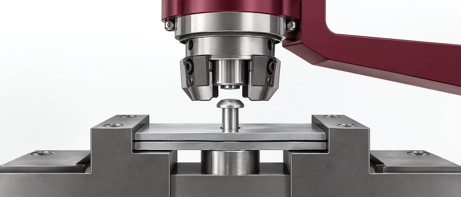
Conceptual equipment illustration.
An orbital riveting machine forms a rivet end through an orbiting tool motion. Choose it from the joint geometry, material and required final function. A formed head of the correct height is useful evidence, but it may not establish the strength or freedom of movement required from the joint.
The process can be evaluated within a custom assembly station. Keep its forming operation distinct from screw fastening or press-fit insertion.
Orbital Is Not Another Name for Radial
BalTec’s forming-process brochure distinguishes orbital, radial and other forming motions, and describes force-stroke monitoring. Those motions create different tool paths; the names should not be used interchangeably in a purchase specification.
Identify the rivet material, protruding length and desired formed profile. Check tool access and the support beneath the joint. A support that moves while the head is formed changes how the force reaches the assembly.
Trial the material and geometry extremes that the station must accept. Do not select a forming unit only from its nominal force rating.
Define the Joint’s Function
For a fixed joint, the acceptance plan may include retention or load testing. For a pivot, it may include movement and permissible clearance after forming. Specify that function directly.
A visual profile check and a functional joint test answer different questions. A part with an attractive formed head can still have incorrect clearance or an internally damaged component.
Compare the assembly route with the press-fit guide where appropriate. Press fitting controls insertion into an interference geometry; riveting creates a retaining form. Their process curves need different interpretation.
Use the Curve to Identify a Forming Cycle
Force and displacement monitoring can distinguish process variation once the instrument and limits have been qualified against acceptable and unacceptable joints. The curve must belong to the correct rivet and part recipe.
Record how the system responds to missing components, incorrect rivet protrusion and a tool that fails to reach its expected state. Confirm where a rejected assembly goes so that rework cannot re-enter accepted flow without the defined check.
The screwdriving and fastening scope offers the comparison for removable joints. Do not choose a permanent forming process if the product requires routine disassembly.
Verify after the Forming Unit Stops
Include the agreed joint-function checks in the automated test equipment interface. If a destructive sample test establishes the process limits, retain its association with the forming setup and material batch.
Contact Motionwell about the joint to discuss workholding, forming and the verification that follows.