
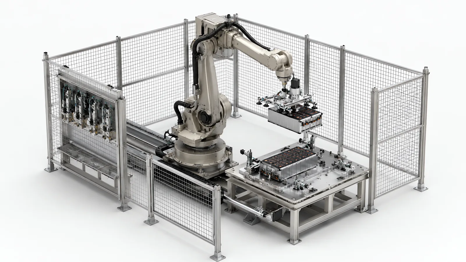
Motionwell Automation builds EV battery disassembly automation in Singapore, from pack fixturing and fastener removal to busbar disconnection and module extraction. The design accounts for residual electrical energy, variable pack condition and recovery from an incomplete operation. Our delivered reference is an EV battery dismantling line built in 2023, with two 200 kg six-axis robots working inside fenced stations. Tooling mass and the load moment at full reach helped set the robot size.
Every safety function on that line is engineered to ISO 13849 Performance Level d. The end effectors are insulated for a pack live at 400 V and above, and modules of 30 to 80 kg are lifted by vacuum-assisted mechanical grippers with load cells that confirm module weight before transfer. Machines are designed, assembled and tested at our Woodlands Link facility, and the company has delivered more than 150 special purpose machines since 2014 under ISO 9001:2015 and bizSAFE Level 3. Who buys this equipment in this region, and what their line has to do, is on the EV battery industry page.
We design everything between the arm and your pack: the tooling, the fixturing, the sequence, the safeguarding, the control system and the recovery logic.
The line itself is documented in the EV battery dismantling case study, and this page builds on it.
Why Does a Live Pack Change Every Safety Assumption?
Because the ordinary way of making an automation cell safe is unavailable. Normally you isolate the energy and then work. A pack arrives with its energy stored inside it and there is no switch that takes it away, so every safeguard has to be designed for a cell that is energised the whole time somebody is near it.
That inverts which object in the room is dangerous. On almost every other cell we build, the arm is the hazard and the safeguarding is drawn around its working envelope. Here the arm is the least dangerous object in the cell. It follows that a force limit on the arm buys nothing: limiting contact energy limits what the robot can do to a person, and says nothing about what the workpiece can do to a person, or about what the robot can do to the workpiece, where an unexpected move could puncture a cell and start thermal runaway. Collaborative rules were deliberately not used to justify an open cell on this line, and the general form of that decision is worked through in our comparison of collaborative and industrial robot cells.
| Hazard in the cell | Why limiting the robot does not address it | What actually controls it |
|---|---|---|
| Stored electrical energy at 400 V and above | Present whether or not anything moves, and present with the power off | Insulated tooling, verified isolation before contact, locked access until voltage is confirmed low |
| Thermal runaway from a punctured or crushed cell | A slower arm still punctures a cell if it goes to the wrong place | Safety-rated axis range and standstill, condition screening before handling, gas detection and extraction |
| Electrolyte vapour and off-gassing | Not a mechanical contact hazard at all | Local exhaust ventilation, continuous gas detection, negative pressure relative to the building |
| Module mass of 30 to 80 kg lifted at extension | Force limiting caps contact force | Arm sized for payload at reach, mechanical guarding, load verified before transfer |
| Electrostatic discharge near exposed terminals | Unrelated to robot speed | Dissipative belt material and bonded grounding through the conveyor structure |
| A pack that arrives already damaged | The robot cannot tell by touching it | Identification and visual condition screening before a gripper is allowed to close |
One collaborative arm does appear on this line, at a vision station inside the larger automated sequence. That is the useful distinction to carry away: collaborative operation is decided per task and per workpiece. Looking at a pack and handling a live one are different jobs with different answers.
The standards route is the same as any machine. An ISO 12100 risk assessment sets what has to be reduced, the robot and the integrated system fall under ISO 10218-1:2025 and ISO 10218-2, and each safety function carries a required performance level calculated and validated under ISO 13849-1:2023. Two things about this line came out of that assessment: every safety function was engineered to Performance Level d with dual-channel monitoring, and the fenced robot stations were separated from the manual loading area at the head of the line, so loading an incoming pack does not put anyone inside the disassembly space. A design still documented against the 2015 edition of ISO 13849-1 will need its performance level calculations restated when the machine is next assessed. The wider compliance scope is on our machine safety and CE marking page.
What Has to Be Proven Before a Person Can Approach the Pack?
It takes a sequence of gates, each producing evidence, with the next step refusing to start until the previous one returns a green status. The order matters more than any individual device in it.
| Gate | What is verified | What stays locked until it passes |
|---|---|---|
| Incoming identification | Pack identity read by barcode, and a visual condition check for swelling or deformation | Entry to the first disassembly station |
| Electrical characterisation | Automated voltage and insulation resistance check on the arriving pack | Any mechanical operation on the casing |
| Pre-disconnection verification | Insulation resistance measured with a Fluke 1587 integrated into the cell controller, in front of every busbar disconnection | The disconnection itself |
| Module separation | Load confirmed against the expected module weight before transfer | Release of the module to the next station |
| Human access | Robot at safe standstill, and area voltage confirmed below 60 V DC by the isolation monitoring relay | Schmersal AZM300 solenoid-locking door interlocks on every access door |
The last row is the one that separates this cell from an ordinary robot cell, and the word doing the work is “and”. Mechanical standstill is not enough. A stationary robot beside an energised pack is a cell nobody should be standing in, so the interlock waits on two independent conditions and the door stays locked until both are satisfied.
The emergency-stop design accounts for robot motion, suspended loads and the pack’s electrical energy separately. Select the stopping function from the robot manufacturer’s supported safety functions, then verify stopping distance, brake behaviour and load retention in the cell’s operating poses. Safe Torque Off removes torque-generating power; the resulting motion depends on the drive, brake and mechanical arrangement. Recovery includes checking the tool and workpiece state, acknowledging the safety circuit and confirming the restart position before movement resumes.
Two of the safeguards on this line protect against the process, and they run whether or not anything is moving. Local exhaust ventilation hoods at each disassembly station extract through HEPA filtration rated at 2,000 m3/h, Draeger Polytron 8000 sensors monitor continuously for hydrogen fluoride and volatile organic compounds, and the line is held at slight negative pressure relative to the surrounding facility so that anything released travels towards the extraction.
What Does “Rated” Actually Mean for Insulated Tooling?
It means a claim about a whole assembly, held to an interval, with somebody’s name against it. It does not mean a material with a number on its data sheet, and the difference decides more than people expect.
On this line every robot end effector and gripping tool is rated for operation in high-voltage DC environments up to 1,000 V, built in three layers that fail differently. An aramid paper wrap is the primary insulation on metallic gripper fingers and tool mounting plates, a material class chosen because it holds its dielectric strength after electrolyte contamination as well as while it is clean, which is the condition the tool is in by month three. A fibreglass laminate bracket sits between the robot flange and the tool body at 45 kV/mm, so the insulation is also part of the load path, which means nobody can remove it to save an hour on a repair. Acetal liners cover the fixture surfaces that touch module terminals, which addresses a different failure: not a person completing a circuit, but the fixture itself bridging positive to negative across a module it is only supposed to be holding.
The part that makes the rating mean anything is the verification interval. Insulation resistance is measured weekly with a 1,000 V DC megohmmeter and any tool reading below 100 megohm comes out of service. Insulation on a working cell degrades by contamination and abrasion, so a tool that passed at commissioning tells you nothing about the same tool in month nine, and a tool that has been re-tipped or repaired has to be re-tested.
The consequence for whoever owns the machine is worth stating plainly, because it is easy to miss at handover. The gripper is a safety function. It belongs in the safety function register alongside the interlocks and the light curtains, and the technician who changes a finger has modified a safety function and needs a procedure that says so. How tooling like this gets designed and built is on our end of arm tooling page.
What Does Module Weight Change About the Handling?
It sets the arm class before any other requirement gets a vote, and it does so through reach. Modules run 30 to 80 kg and have to be lifted at extension inside a pack, so the useful number is payload at reach with the tooling attached. Rated payload is measured at the tool flange, which means the insulation, the nutrunner and the gripper structure all come out of the same budget the module needs. That is how a 30 to 80 kg module ends up on a 200 kg arm.
The gripper naming on this line is the design in miniature: vacuum-assisted mechanical grippers, in that order. The mechanical element carries the load and the vacuum assists, which is the right way round on a coated, vented, sometimes contaminated casing where a vacuum cup has no guarantee of a clean sealing surface.
The load cells are the more interesting part, and they are not a lifting check. They confirm module weight against expected values before transfer, which makes weight a state check on an assembly nobody can see inside. A module that reads heavy is usually still fastened to something. A module that reads light is not the module the recipe expected. Either way the cell has learned something about the pack before the module is in the air, and that is a cheap diagnostic on a workpiece that cannot be opened for inspection.
Transport carries its own constraints. The line runs a heavy-duty belt conveyor rated for 500 kg per pallet position, with zero-pressure accumulation zones for transfer between stations and a three-position accumulation buffer between disassembly and sorting so the two ends do not have to share a cycle time. Zero-pressure accumulation is the part worth insisting on: on an accumulating conveyor the waiting pallets push on the one in front, and a 500 kg pallet leaning on its neighbour puts that load path through an energised pack. A belt, and no driven rollers, follows from the same load, because the pallet is carried on a continuous surface, and the base of a pack fixture is rarely flat and rarely rigid. The belt surfaces are carbon-fibre-loaded PVC with surface resistivity in the dissipative range under IEC 61340-5-1, and grounding straps bond the conveyor frame to the facility ground bus every 3 m, so charge bleeds away continuously, and never accumulates to discharge near an exposed terminal. Where a machine of this kind incorporates lifting equipment, it has to be examined and certified by an approved authorised examiner before use in Singapore, which we handle as part of delivery.
How Do You Fixture a Pack That Is Not Perfectly Consistent?
You start by accepting that the incoming mix is not under anyone’s control. A recycler takes what arrives, so the fixture cannot be designed around one pack the way an assembly fixture is designed around one product.
The delivered answer is a reconfigurable base plate: a grid of M8 threaded inserts on 50 mm centres, with Destaco pneumatic swing clamps of adjustable stroke and clamping force repositioned against that grid, and 3D-printed Nylon 12 locating nests carrying the module-specific features. The plates are anodised aluminium 6061-T6, chosen for two reasons that both matter here: the strength-to-weight ratio lets a technician reposition a plate by hand, and the material is non-magnetic, which keeps the fixture from interfering with battery management system electronics during disassembly. Changing between prismatic and pouch module formats means repositioning the clamps and updating the clamp-position recipe in the PLC, about 30 minutes with two technicians, with no welding, drilling or permanent modification.
Flexibility is not free and it is worth being explicit about the bill. Dedicated nests for a single format would clamp faster, locate better and need no recipe management at all. What the grid buys is the ability to accept a format that was not on the drawing when the line was built, and what it costs is the changeover time above and a clamp-position recipe that has to be right, because a mislocated module is a mechanical interference on a live pack. The same trade appears on packaging equipment in a lower-consequence form, set out on our filling line changeover page.
Why Is Taking a Pack Apart Harder Than Putting One Together?
Because assembly knows the state of every part before it touches it, and disassembly does not. This is the single assumption that has to be surrendered when a line runs in reverse, and most of the engineering difficulty follows from it.
| What an assembly line assumes | What a disassembly line finds |
|---|---|
| Parts arrive to a drawing and to a tolerance | The pack arrives as it comes back from service, with a history nobody recorded |
| Fasteners are new, clean and correctly torqued | Fasteners may be corroded, painted over, preloaded, or already rounded |
| The joint was designed to be made | The joint was designed to survive vibration and crash loads for a decade |
| The sequence is fixed and repeats | The sequence has to branch on what is found, including the branch where a fastener will not move |
| A failed operation produces a scrapped part | A failed operation is happening on an energised assembly |
| Adhesive and sealant are process steps | Bonded joints have no reverse operation at all |
The instrumentation answers the first four rows. Atlas Copco QST torque-controlled nutrunners mount on the robot flange, with torque and angle logged per fastener against the pack barcode. On an assembly line that record proves a joint was made correctly. In disassembly the same signal has to work as a detector, and a fastener that has not broken loose within the expected angle window should be a stop condition, because the alternative to stopping is a rounded head on a live pack and a manual recovery task nobody wanted.
The last two rows are why the delivered line stops where it does. Its scope ends at module separation, and cell-level teardown, electrolyte handling and cathode processing were deliberately left outside it. Automating those means treating breached cells as a normal operating condition, which is a different machine with a different fire case behind it, and drawing that boundary is usually the most consequential decision made on a project of this shape. How that scoping conversation runs before a design exists is on our custom automation page.
How Does Vision Find a Fastener on a Pack That Varies?
It finds one by supplying an offset. Teaching a fixed position works when the fixture holds the same part in the same place every cycle, which is exactly the condition a reconfigurable grid gives up. So the camera locates the features on the pack in front of it and the robot corrects to them, and the program assumes nothing about where they ought to be.
Vision has two separate jobs to do on a battery dismantling line and they fail in different ways. The first is identity and condition at the head of the line, where the barcode read and a visual condition check share the same camera and lighting approach: a swollen or deformed casing has to be caught before a gripper touches it, which makes that station a safety interlock wearing a camera. The second is feature location during disassembly, where fastener heads, connector bodies and busbar terminations have to be found on a casing whose position and revision both vary.
What decides whether the second job works is presentation and lighting, since a defect or a feature the light does not reveal is invisible at any resolution. Battery casings make that harder than average: dark anodised and painted surfaces sit next to specular busbars and fastener heads in the same field of view, and fasteners frequently sit recessed below a surface that shadows them. Those are lighting geometry problems, solved at the station, and the approach we take to them is set out on our machine vision inspection page.
State the limit clearly, because on a battery line the temptation to over-read a vision result is real. A camera cannot see state of charge, an internal short, or the condition of a cell through its casing. The electrical checks do that work. Vision confirms geometry and identity, and a vision pass must never be wired into the sequence as though it were an electrical clearance.
What Has to Be Recorded, and at Which Level?
Records are kept at pack and module level, with the awkward requirement that the record has to survive the pack ceasing to exist.
Traceability on an assembly or packaging line builds parents from children: units into cases, cases onto pallets, each link written as the parent is formed. Disassembly runs that chain backwards and hits a problem the forward direction never has. The parent identity is the only identity that arrives at the door. Every child leaves the line as an independent item, and if a module leaves without a record binding it to the pack it came out of, its history is gone. For material recovery that may not matter much. For anything sold on, that history is part of what the buyer is paying for.
The delivered line binds records to the pack barcode, including torque and angle for each fastener operation. At module separation, preserve that parent identity on the extracted modules and record the separated casing and busbar components. Cell teardown and recovery of cathode or anode material belong to the downstream recycling process. The identity scheme connects these stages without treating material recovery as an operation performed by the dismantling cell. The read side is covered on our code reading and traceability page.
The battery-specific difficulty is that a module’s own identity is often not machine-readable, or not there at all. It may be a label under a bracket, a marking never intended for a camera, or nothing. Where no readable module identity exists, the line has to create one at the point of separation, and that is a specification decision, because adding a marking station afterwards is a rebuild of the sorting end.
How Do Second Life and Recycling Change the Machine?
They are different end states, and the difference lands on the machine. A line built for one is not a line for the other with a label changed.
| Requirement | Material recovery | Second life |
|---|---|---|
| What leaves the line | Separated material streams | An intact, working, graded module |
| Damage on the way out | A nuisance, since the module is going to be broken down anyway | A loss of the whole value of the item |
| Electrical test depth | Enough to make handling safe | Enough to grade capacity, resistance and state of health per module |
| Identity and record | Bound to the pack for process and compliance | Bound to the module, and durable enough for a downstream buyer to accept |
| Fixture and gripper priority | Speed and separation quality | Non-marking, non-deforming handling of a saleable item |
| Sorting logic | By material | By grade, and by whatever the receiving application will accept |
| What limits throughput | Disassembly and separation | Test time per module, which no faster arm shortens |
Our delivered work sits at the material recovery end. What transfers from it to a second-life line is the whole front half: identification, electrical verification, safe opening, fastener removal and module extraction are the same problem up to the moment the module is off the pack. What does not transfer is the back half, and the back half of a second-life line is largely test work, which is automated test equipment work with a different specification, a different cycle time and a different data model behind it. Anyone scoping a second-life line as a dismantling project with testing added at the end has the proportions the wrong way round.
When Is a Robot Cell the Wrong Answer for Battery Work?
Four situations put the answer somewhere other than a robot cell, and each is worth recognising before a layout is drawn.
The volume does not exist yet. Where a handful of packs a week arrive across many formats, a trained team with insulated hand tools and a proper permit-to-work system will beat a machine on cost and on flexibility, and the reconfigurable fixturing that makes a machine flexible is exactly the part that costs money and changeover time. Automation earns its place when a format repeats often enough for a recipe to be worth having.
The formats change faster than a recipe can follow. A clamp grid absorbs variation within a family. It does not absorb a genuinely new pack architecture every month, and pretending otherwise produces a machine that is in changeover more often than it is in production.
The joining process sets the assembly scope. Pack-assembly projects need the joining method, process equipment and acceptance tests defined separately from the handling and controls. A specialist welding supplier owns the weld process; the pack fixtures, transfers and control interfaces are scoped around that equipment.
You want the cell to run unattended. Lights-out is not a realistic target where a fault means somebody eventually approaching an energised assembly. Design for recovery instead: what the cell does when a fastener will not move, who opens the door, and what has to be proven before they do. A line that stops safely but needs an engineer to clear it will be worked around by the third shift within a month.
One boundary beyond the machine is worth naming early. Our scope ends at the cell and its extraction. How incoming packs are stored, at what state of charge, and under what fire strategy is a building question answered with your own fire safety consultant and the authority having jurisdiction, and it usually needs to be settled before the layout is fixed.
Which Parts of This Would You Actually Need?
Many enquiries turn out to need some of the line. The table below is how we sort them at the first conversation.
| Your situation | Start from | Why |
|---|---|---|
| Packs arrive in a mix nobody controls | Reconfigurable clamp grid and a clamp-position recipe | The fixture cannot be designed around one pack, and the changeover is the price of accepting that |
| One pack format at volume | Dedicated locating nests | Faster clamping, better location and no recipe to manage |
| Output goes to material recovery | Separation quality and stream sorting | Damage in transit costs little, so the design optimises for safe throughput |
| Output goes to second life | Per-module characterisation and a durable module identity | Test time sets the rate, and the record is part of the product |
| Operators open packs by hand today | The safety case, before any robot is selected | The hazard inventory decides the guarding, the tooling and the sequence |
| Busbar joining by welding | A welding process supplier | Joint design, welding parameters and joint validation need a specialist joining process |
Lead time runs 16 to 24 weeks from concept approval to factory acceptance testing on a standard build, and design, fabrication, assembly and testing happen at Woodlands Link, which is why a Singapore buyer attends the factory acceptance test without flying to it. On a line of this kind that matters more than usual, because the details that decide whether it runs are found on your own packs.
Standards Used in Machine Design and Validation
These references inform the design, testing and documentation described on this page. Each row links to its primary source and records the edition checked.
| Standard | Current edition | What it means for your machine |
|---|---|---|
| ISO 10218-1: Robotics, safety requirements, Part 1: industrial robots | ISO 10218-1:2025 | Published February 2025, the third edition and the first substantive revision since 2011. It adds robot classifications with matching functional safety requirements and safety-related cybersecurity requirements. Most of ISO/TS 15066:2016 on collaborative operation moved into Part 2.Checked 12 Sep 2026 against ISO 10218-1:2025 (iso.org/standard/73933.html) |
| ISO 13849-1: Safety of machinery, safety-related parts of control systems | ISO 13849-1:2023 | Provides the design method for safety-related control functions, including architecture, component reliability, diagnostic coverage and common-cause failure measures. The machine risk assessment establishes the required Performance Level; design calculations and validation provide the evidence for each function.Checked 1 Sep 2026 against ISO 10218-1:2025 normative references |
Frequently Asked Questions
What do you need from us if the pack manufacturer will not release drawings?
A physical pack and permission to take one apart, which is what the design actually gets built from. Drawings help and we ask for them, but a dismantling line is designed against fastener positions, joint types, harness routing and the way a casing actually comes off, and none of that is reliably readable from a model of the assembled state even where one exists. What we need is at least one representative pack per format, its nominal voltage and its arrival state of charge, and a written account of how your people handle it today. A proving trial on real packs turns an opinion about feasibility into a number, and we would rather run it before quoting than after.
Can an assembly line be reversed to run disassembly?
Rarely as it stands, and the reason is structural. An assembly line moves from known parts to a known product, so its fixtures locate features guaranteed to be there and its sequence never branches. A disassembly line receives one item whose internal state it cannot assume, and has to branch on what it finds, including the case where a fastener will not come out. The station order can sometimes be reused, and the frames, conveyors and control hardware often can. The fixturing, the tooling and most of the control logic get redesigned. Control system modernisation of existing production machines is our largest line of work this year, so partial reuse is worth assessing.
How many packs per hour should a robotic dismantling cell run?
Ask for a different number, because parts per hour measures the wrong thing here. Cycle time was never the selection criterion on the delivered cell and could not have been: a voltage and insulation resistance verification step runs in front of every disconnection and takes as long as it takes, so a faster arm does not compress it. The figures worth putting in a specification are packs per shift against a stated format mix, the changeover time you can live with, and how much of the sequence has to complete with nobody inside the cell.