
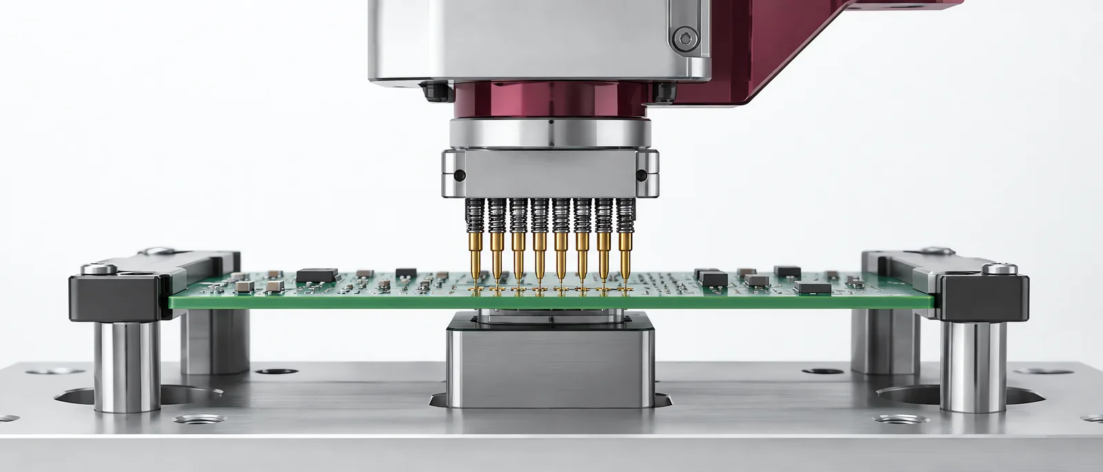
Conceptual equipment illustration.
A pin insertion machine must place the intended pin into the correct hole without damaging the pin, board or housing. Select the tooling from the pin design and receiving geometry, then establish alignment and support. The insertion force is meaningful only in that configured load path.
This is a specific task within custom automation, not a generic purchase defined by press force alone.
Specify the Pin and Receiving Part Together
For a PCB, identify hole size, plated construction, board thickness and the pin’s intended insertion feature. A compliant press-fit pin and a pin intended for later soldering do not have the same assembly requirements.
TE’s pin-insertion overview describes application-specific tool packs and force-monitoring options on selected equipment. Their inclusion needs to be confirmed for the actual machine configuration.
Keep the receiver supported near the insertion load path. Check that the support clears existing components and does not bend the board before insertion. A board that flexes under the tool can change both the position and the recorded force.
Alignment Comes Before Force Limits
Use board or housing datums that relate to the receiving holes. Verify positioning through the range of part variation and fixtures that will be used in production. Camera correction, where included, needs a defined relationship to the insertion tool.
A press-fit machine follows the broader force-position principle. Pin insertion adds a need to control delicate contact geometry, board support and pin feeding.
Trial a wrongly presented pin, a missing hole/pin and the permitted dimensional extremes. Record what the station can distinguish. Do not learn limits from one perfect assembly and assume they detect every damaging condition.
Final Seating and Contact Need Separate Evidence
The process record should identify the pin type, receiving-part revision and inserted location. Inspect final seating with the measurement relevant to the design. If the functional requirement includes electrical continuity or another contact characteristic, test it separately.
A normal force curve cannot establish every electrical characteristic of the connection. Use the automated test equipment interface to associate those checks with the assembly.
For electronics manufacturing, keep a clear route for rejected boards and interrupted insertion cycles. A restart must know which locations were completed so that the machine does not attempt to insert a second pin into an occupied hole.
Discuss the pin insertion task with Motionwell to plan feeding, workholding and result verification together.