
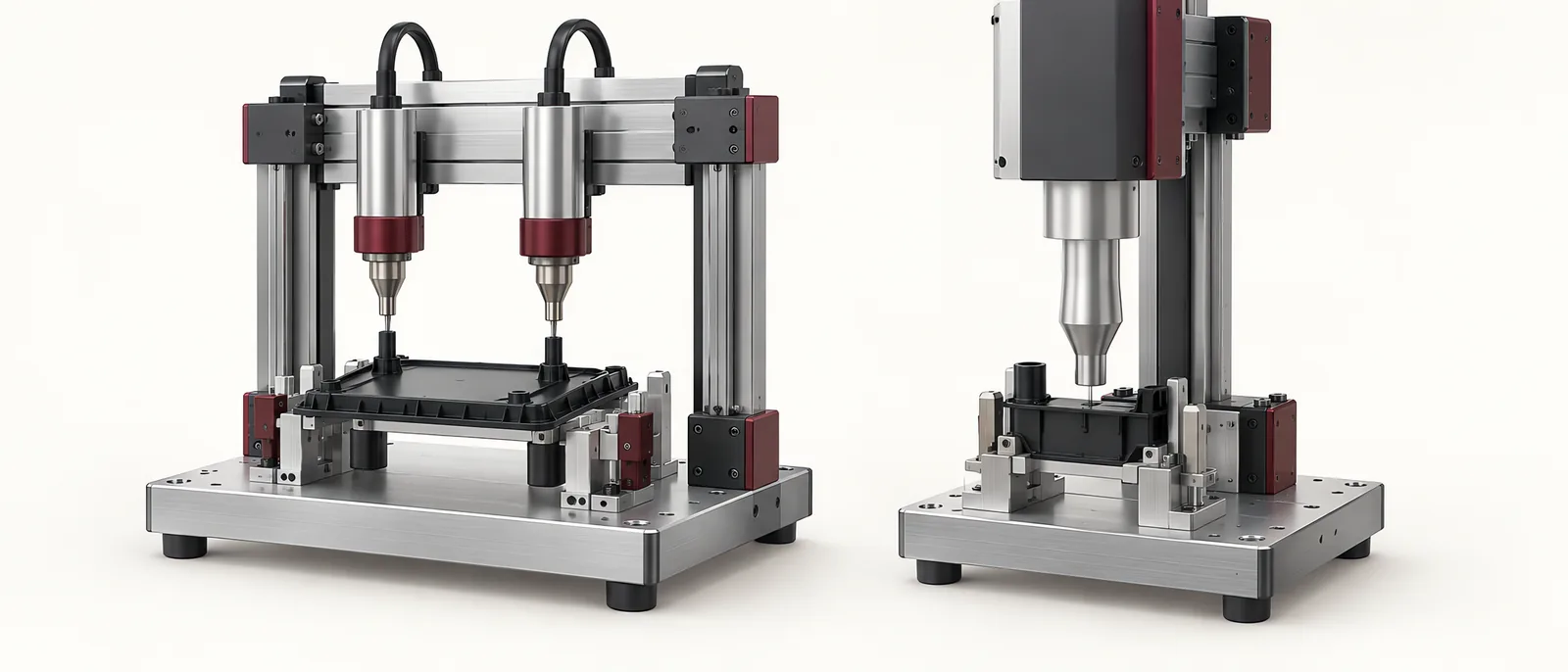
Conceptual equipment illustration.
The main difference in heat staking vs ultrasonic welding is the joint being made. Heat staking reshapes a thermoplastic post to retain another component mechanically. Ultrasonic welding joins suitable thermoplastic surfaces through local heating and fusion at a designed interface.
Choose the required joint function first. Holding a circuit board inside a housing is different from joining two housing halves around a sealed perimeter. A process comparison is useful only when the proposed joint geometry supports that function.
Mechanical Retention or Material Fusion?
A heat-staked post passes through or around the retained component and is formed into a head. The retained component can be a different material because retention comes from the post geometry. The design must provide enough material and space for the formed head.
In ultrasonic plastic welding, vibration is delivered through the tooling into the parts, generating heat at the joining interface. Material compatibility, joint design and support affect the result. Branson’s explanation of ultrasonic plastic welding describes this local melting and subsequent joint formation.
Ultrasonic staking is a separate distinction. It uses ultrasonic energy to form a retaining feature. Comparing thermal staking with ultrasonic staking is not the same as comparing staking with a welded seam. Dukane’s thermal-versus-ultrasonic staking guidance addresses that staking comparison, including tooling geometry and vibration-sensitive assemblies.
A Joint-First Selection Table
| Requirement | Heat-staking route | Ultrasonic-welding route |
|---|---|---|
| Retain metal or a PCB in a plastic housing | Review post location, head geometry and retained-part support | A conventional plastic weld does not directly replace the retaining post |
| Join compatible plastic housing halves | Individual stakes may retain the halves but do not create a continuous welded seam | Evaluate a suitable interface and access for the horn and fixture |
| Preserve a cosmetic face | Check heat-tool contact and material displacement | Check horn contact, marking and energy transmission |
| Work around sensitive internal components | Evaluate local heating and mechanical load | Evaluate transmitted vibration and assembly support |
| Require a leak-tight joint | Retention alone does not establish sealing | Design and verify the complete sealing interface |
Use the relevant joint requirement to select samples and tooling for the process trial.
Tooling Can Decide Feasibility
For staking, inspect post heights, spacing and access for the forming tool. Posts on different planes can require a more involved tool arrangement. For welding, examine how the horn contacts the part and how the fixture supports the joint during the cycle.
A thin housing can deflect under either process. Keep the functional surfaces supported and inspect the finished assembly for movement or distortion. On a medical-device assembly machine, include the downstream dimensional or functional requirement in the joining trial.
Compare Complete Cycles
Include loading, clamping, heating or vibration, hold or cooling, release and result checking. A short energy-application time does not necessarily make the complete station the faster option.
When the joining step sits on a rotary indexing assembly machine, assess its effect on the other stations. If it controls the index time, evaluate parallel tooling or a different process arrangement using the actual trial result.
An adhesive joint is another design route when the product requirements suit it. It introduces its own surface preparation, dosing and cure considerations, covered in dispensing and adhesive systems.
Decide With Matched Samples
Use the intended materials and geometry. Compare retention or joint strength, dimensions, appearance and any required leak or functional test. Record the process settings and tooling revision with each sample so that an attractive demonstration can become a repeatable production method.
Motionwell’s custom automation scope covers integrating a selected joining process into the machine sequence. Discuss your assembly with us.