
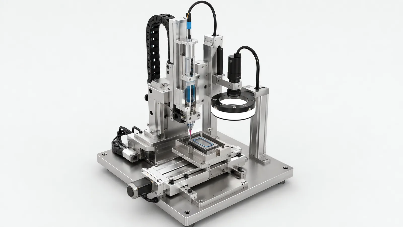
Motionwell Automation builds adhesive dispensing systems in Singapore as process stations, and never as a valve bolted to a bracket. The delivered work behind that sits on pharmaceutical and electronics equipment: a pharmaceutical dispensing unit with cartridge and pump assemblies, whose dispensing head is built around a precision linear stage with a stainless steel metering valve and a Luer-lock needle, and adhesive application as one of the station types on a vision-guided SCARA sensor panel assembly line, alongside connector insertion and component placement. Valves, pneumatics and vision hardware are bought in, and the selection rule on a dispensing station is narrower than on most machines: every wetted item has to survive both the material and the solvent the material supplier names, and every one of them has to be a catalogue item your storeman can reorder against a part number, because a diaphragm or a seal that only we can supply is a line stoppage waiting for a shipment. Machines are designed, assembled and tested at our Woodlands Link facility, and the company has delivered more than 150 special purpose machines since 2014 under ISO 9001:2015 and bizSAFE Level 3.
Your material supplier owns the chemistry, the cure schedule and the shelf life. What we design is the station that puts that material in the same place, in the same quantity, on every cycle, and proves that it did. One scope line is worth drawing early because the two get quoted against each other: a dispensing system applies a bead, a dot or a film to a part, while a filling machine puts a measured dose into a container. The pumps look similar and the acceptance criteria are not, so if a container is what you are dosing, the filling machines page is the one you want.
How Do Metering and Motion Set the Bead Cross-Section?
For a continuous bead, deposited cross-sectional area follows volumetric flow rate divided by path velocity. The metering system controls flow through the material path; the robot or gantry controls travel speed. Coordinate the two through starts, stops and corners so deceleration does not leave a thicker bead. Material temperature, viscosity and nozzle condition also affect the result and belong in the dispense recipe and verification trial.
| Variable | What it does to the bead | Why it moves on a real line |
|---|---|---|
| Viscosity at dispense temperature | Sets flow rate at any given driving pressure | Room temperature across a day, drive and valve heat, product taken straight from cold storage |
| Thixotropy and shear history | A shear-thinning paste flows more freely once it is moving, so the start of a move differs from the middle | Dwell time between parts, and how long the material has been sitting in the line |
| Needle standoff, the Z gap | Decides whether the bead is laid down, dropped in, or dragged and wiped | Part flatness, fixture wear, warped or stepped surfaces, tolerance stack on the nest |
| Path velocity | Divides into flow rate to give the cross-section | Every acceleration, deceleration and corner in the programme |
| Valve open and close latency | Sets where material actually starts and stops relative to the taught path | Air line length and volume on a pneumatic valve, and material back-pressure |
| Needle bore condition | Changes the restriction, so the same pressure gives a different flow | Partial cure at the tip, filler build-up, physical damage from a touchdown |
| Material batch | Viscosity and filler distribution vary batch to batch within the supplier’s own specification | Incoming supply, which is outside both our control and yours |
Two consequences follow, and they are why the station gets designed differently from a pick and place. First, the rows interact, so a bead corrected by raising pressure and a bead corrected by slowing the path are not the same bead, even when both measure the same width. Second, the machine will accept a compensating change at the operator panel and give no signal that the material underneath it moved, so a station with no record of its own settings loses the original recipe within a few weeks of ordinary tuning.
Which Dispensing Technology Suits Your Material?
Valves are classified by how the material is metered, never by what they look like on a bracket. Five families cover most industrial work, and the material narrows the list before anything else does.
| Metering method | How it meters | Suits | Where it struggles |
|---|---|---|---|
| Time and pressure | Regulated air pressure on a syringe or reservoir for a controlled time | Low to medium viscosity, tolerant bead width, low capital cost, easy cleaning, no wetted mechanism | Open-loop: flow drifts with temperature, head height and needle condition, so it needs verification or frequent re-tuning |
| Auger, rotary screw | A turning screw meters a volume per revolution | Filled pastes and solder paste, small repeatable dots, materials too viscous for pressure alone | Abrasive fillers wear the screw and chamber, which is a consumable and a drift source |
| Progressive cavity | A rotor turning inside a stator carries sealed cavities of material forward | Viscous and shear-sensitive materials, long continuous beads, low pulsation | Rotor and stator are wetted wear parts, and the stator elastomer has to be compatible with the material |
| Positive-displacement piston | A piston sweeps a fixed volume per stroke, independent of upstream pressure | Repeatable shot volume where the dose matters more than the path, and materials whose viscosity moves | More wetted parts to clean, seal wear, and a refill stroke that has to be hidden inside the cycle |
| Jetting, non-contact | The valve fires discrete drops across an air gap | Delicate or recessed features, fast dot patterns, dispensing without stopping the head | Material has to suit the valve, the valve is a service item, and satellites or misplaced drops appear when standoff or material is wrong |
The distinction that matters most on that table is pressure-driven against displacement-driven. A pressure-driven valve commands a condition and hopes for a volume. A displacement-driven valve commands a volume and pays for it in wetted parts, cleaning and seal maintenance. Which trade is correct depends on the consequence of a bad bead.
Our own delivered pharmaceutical dispensing unit was built with that trade in mind. It is fed from cartridge and pump assemblies, and its head carries a precision linear stage with a stainless steel metering valve and a Luer-lock needle, a construction chosen so the wetted path can be dismantled and cleaned. That reasoning and the rest of the pharmaceutical packaging equipment scope belong together.
For a plastic housing, compare adhesive joining with heat staking and ultrasonic welding by the function of the joint. Mechanical retention, fused seams and bonded interfaces impose different geometry, preparation and verification requirements.
Why Does a Time-Pressure Valve Drift Across a Shift?
Because flow through a restriction depends on the pressure difference across it, the viscosity of what is flowing and the size of the opening, and a time-pressure system controls only the first of those. Everything else is free to change while the recipe stays the same.
Three drifts stack over a shift, and they do not cancel. The fluid column above the needle falls as the syringe or cartridge empties, so the static head which adds to the driving pressure falls with it. The material warms, from the room, from a valve body sitting next to a heat source, or simply from a cold cartridge reaching ambient, and warmer material flows more freely at the same pressure. And the needle bore narrows as material partially cures at the tip or filler builds up on the wall, which pushes flow the other way. The result is a machine that lays a different bead in the last hour than it did in the first, with nothing on the HMI reporting a change.
What this means for how the shift is run is more important than the physics. A first-off sample that passes at the start of a batch is evidence about the start of a batch, and nothing else. There are three defensible responses: verify a shot at an interval and correct against the measurement, move to a displacement-metered valve where the volume does not depend on the pressure, or accept the drift because the bead specification is wide enough to absorb it. The third is legitimate and cheap. It just has to be a decision.
Time and pressure keeps its place for good reasons: no mechanism in the wetted path, the fastest cleaning of any family, a low enough capital cost that several stations can carry one each, and adequate control where the tolerance band is wide. On a low-consequence bond with a generous specification it is often the right buy. On a bond that is invisible after assembly it is the family that most needs the verification section below.
When Does Non-Contact Jetting Earn Its Place?
It earns its place when the needle must not touch the part, or cannot reach it. A jetting valve fires the material across an air gap, which removes the two constraints that shape every contact dispense: the Z standoff has to be right, and the needle has to physically fit.
Four situations where that buys something real. A delicate surface, such as a membrane, a lens, a thin panel or a populated board, where a needle touchdown is itself the defect. A recessed feature, where the bead belongs in a pocket a needle body cannot enter without a dedicated Z move per dot. A part whose height varies, warped, stepped or held in a nest with a tolerance stack, where a contact dispense needs Z tracking to keep standoff constant and a jet is far less sensitive to it. And a dense dot pattern at rate, because a jet can fire while the head keeps moving, with no stopping, settling and lifting for each dot.
The costs are specific enough to check before ordering. Not every material jets: viscosity, filler particle size and the material’s own tendency to string decide whether the valve produces a clean drop or a tail. The valve is a service item with a nozzle, a seat and a seal that wear, so its consumable interval belongs in the maintenance schedule at design stage. Standoff still matters, because although the jet tolerates a wider band than a needle does, drops go astray outside it. And heated jetting introduces a hot component sitting where an operator’s hands go, which is a safety question.
After selecting a jetting route, qualify the actual valve/fluid combination. jet valve process window covers deposit quantity, stand-off, cleaning and restart.
What Changes When the Material Is Two-Part?
The machine acquires a material that hardens inside it, which is a different class of design problem from moving a fluid from A to B. Three properties drive everything: the mix ratio has to be held, the pot life is a clock that starts at the mixer, and the cure that makes the joint work also destroys the machine’s own wetted path if the material stops moving.
| Route | How it works | What it provides | Costs and constraints |
|---|---|---|---|
| Pre-mixed and frozen | Supplier mixes and freezes the material; the machine dispenses a single component | No mixing hardware, no ratio to prove, no meter-mix cleaning | Cold chain, thaw handling, a working life once thawed, and a supplier who offers it |
| Static mixer with disposable nozzle | Two streams meet in a helical mixing element that is thrown away before it cures | Cheapest mixing hardware, no cleaning of the mixer at all | A consumable per changeover or per pot life window, plus the purge material that primes each new nozzle |
| Dynamic meter-mix-dispense | Each component is metered separately and mixed in a driven mixing head | Ratio control and the widest material range | The most wetted parts, a solvent or purge routine, and a machine that must not be left idle mid-batch |
Two design consequences fall out of that table. The first is that ratio needs its own evidence. Off-ratio material mixes, dispenses, looks correct and cures to the wrong properties, so a joint that fails a pull test weeks later traces back to a ratio nobody measured. Ratio verification, whether by periodic shot weight on each component, by pressure monitoring on both lines, or by a documented gravimetric check at start of batch, is a specification line.
The second is that idle time becomes a machine state. A machine holding a mixed two-part material has a countdown running, and the purge that protects it has to be triggered by elapsed time since the last shot, with the interval taken from the material’s pot life in the PLC. A line stop at lunch, an upstream jam or an unplanned meeting are all events that can end a mixing head.
Cure time is the other thing to place early. A cure measured in minutes does not belong inside a machine whose stations all index together, which is the same argument we make about any long dwell on the rotary indexing versus inline assembly page: it goes offline, into a parallel bank, or onto a conveyor buffer. And a bonded joint has no reverse operation, a point we treat as a design constraint on the battery module automation page, where adhesive and sealant are the steps a disassembly line cannot undo.
Filling a component cavity adds mixing, trapped-air and cure requirements. epoxy potting requirements distinguishes those checks from visible bead deposition.
Why Does a Corner Come Out Heavy?
Because the valve does not know the axis is slowing down. A path programme decelerates into a corner, changes direction and accelerates out of it. If flow rate is held constant through that, the same material per second lands on fewer millimetres per second of travel, and the bead thickens exactly where a designer usually wanted it thinnest. On a closed gasket path, the corners are also where the seal is most likely to be tested.
Four ways to deal with it, in roughly the order they should be tried.
Slave flow to velocity. The clean answer is to drive the valve from the actual or commanded path speed, so flow falls as the axis decelerates. A motion platform that cannot publish path velocity, or expose a trigger proportional to it, cannot do this at all, and the three items below are workarounds for its absence.
Round the corner in the path. A programmed blend radius at the corner keeps velocity higher through the turn instead of dropping it to a near stop. It changes the bead geometry slightly and it is usually the cheapest improvement available.
Break the path. Stop the flow before the corner, reposition, and restart. It costs cycle time and introduces two more start and stop transitions, each with its own valve latency to compensate, so it suits low corner counts.
Lead and lag the valve. Opening slightly before the start point and closing slightly before the end point compensates for the delay between the command and the material arriving. These offsets are properties of the material, the line volume and the valve, which is why they get re-established when any of the three change.
Underneath all four sits the motion quality of the machine carrying the valve, and it is easy to under-specify. Vibration during a bead shows up directly as inconsistent width or dot size, which is the reason we discuss direct-drive joints and backlash in the path in our note on SCARA robots in electronics assembly. A contour on a curved surface needs a wrist that can hold the needle normal to the surface, which a three-axis frame cannot do, as set out in our gantry against six-axis comparison. And an open-loop axis that loses a step reports the commanded position while the bead lands somewhere else, a silent failure covered in our comparison of servo and stepper motor drives.
How Do You Prove the Dispense Actually Happened?
This is the part of the station that gets cut from a budget and is the reason to build it. An unverified dispense is a latent defect: material is dispensed, the part is assembled over it, the joint cures, and the evidence is now inside a finished product. A missing bead is not visible, a thin bead looks like a normal bead, and off-ratio material looks like correctly mixed material. The cost is not scrap at the station. It is a functional failure downstream, a field return, or a batch nobody can bound.
| Verification method | What it catches | What it misses | What it costs in the cycle |
|---|---|---|---|
| Shot weight on a balance | Metering drift, blocked needle, air in the line, off-ratio on a component check | Anything about placement, since the material never reaches the part | A purge shot at an interval, plus a stable weighing position and a waste route |
| Vision bead inspection | Presence, continuity, width, position relative to the feature, gaps and breaks | Depth and volume in most 2D setups, and anything under an opaque overlay | An image and a decision inside the station cycle, plus controlled lighting |
| Valve and line monitoring | Pressure loss, an empty cartridge, a valve that failed to actuate | A bead correctly dispensed to the wrong place | Almost nothing, since the signals are already on the machine |
| Downstream functional or leak test | Whether the joint does its job | Which station caused a failure found three operations later | A test station, and a longer feedback loop to the cause |
The four are not alternatives, and the useful combination is usually the first two. Weight tells you how much material left the valve and nothing about where it went; vision tells you where it went and very little about how much. On assemblies where the bead is a seal, both matter enough to justify both.
What makes bead inspection work is what makes any inspection station work, and it is not sensor resolution. A defect the light does not reveal is invisible at any resolution, so contrast on a translucent bead against a similarly coloured substrate is a lighting geometry problem solved at the station, and the part has to be located mechanically so the camera is not reading a rocking nest as a displaced bead. The method is on our machine vision inspection page. Speed is rarely the obstacle: on the vision-guided sensor panel assembly line the inspection routine completes in under 50 ms per station, which keeps the check inside the robot cycle, and that is the number worth specifying, since an inspection that runs longer than the move it follows turns a quality gate into a rate penalty and gets quietly switched to sampling. The build is described in the SCARA panel assembly case study.
Where the dispensed fluid is the product, the same argument holds on the tray-fed filling and sealing machine we delivered: a camera checks the fill level after the three dosing heads and the seal after the sealing station, so the dose and the closure are each proven separately, and a failed unit is rejected before it reaches the output tray.
What Do Temperature, Purging and Cleaning Have to Be Designed In For?
They are designed in because the material is alive, and the machine is not the only thing that has to survive a weekend.
Temperature control is a process instrument. Since viscosity moves with temperature and flow moves with viscosity, holding the material at a temperature removes one of the drift terms in the first table on this page. That can mean a heated cartridge or reservoir, a heated valve body, a temperature-controlled material line, or simply a conditioned bay. Singapore ambient makes this less optional than it is in a temperate plant, because a station standing in an unconditioned bay under a metal roof sees a genuine swing between a night shift and a hot afternoon while a station inside a conditioned cleanroom does not. Which of those two your machine will stand in is a specification line.
Purge is a designed function with somewhere for the waste to go. A purge routine needs a defined trigger, a target, a container and a disposal route. Triggers worth putting in the specification are start of shift, resumption after an idle period, a cartridge change, and the first part of a verified batch. The target is a purge pot or a waste position, and it needs to be reachable inside the cycle so the operator is not asked to jog the machine to it. The waste itself is a consumable cost and, for some chemistries, a disposal obligation.
Cleaning access decides how long a changeover takes. Every wetted part is a surface that has to be cleaned, inspected and eventually replaced, so the wetted path wants to come apart without tools and go back together without a torque spanner. Where the dispensed material is a pharmaceutical product, that requirement becomes a construction specification: on the filling and sealing machine we delivered, product-contact surfaces are stainless steel finished against the cleaning chemistry the customer uses, the format parts come off without tools, and the whole machine was designed to stand in an ISO Class 7/8 room. In a classified zone, the solvent and the wipe-down routine become part of the cleanroom equipment design.
Needle and nozzle maintenance is a scheduled item. A tip wipe station, a defined needle replacement interval and a nozzle service interval on a jetting valve cost very little at design stage and are difficult to retrofit into a station already running, because each of them needs a position, a cycle and somebody to own the schedule.
Which Safety Points Are Specific to a Dispensing Cell?
Three, and the first one surprises people who arrive expecting a collaborative arm.
A force-limited arm limits contact force. It does not limit anything about what is in the tool. A heated hot melt at dispensing temperature, a reactive or sensitising chemistry, a solvent vapour and a pressurised material line are hazards the arm cannot reduce, which is why a dispensing application on a collaborative platform still needs its own assessment against the tool and the material, never against the robot’s published figures. ISO 10218-1:2025, the third edition and the first substantive revision since 2011, added end-effector guidance alongside robot classifications and safety-related cybersecurity requirements, and most of what ISO/TS 15066:2016 said about collaborative operation moved into Part 2, so a safety file written for a dispensing cell this year should name the edition it is actually assessed against.
The second is ventilation and extraction, which is a building question as much as a machine question. Solvent vapour, heated material fume and purge waste all have to go somewhere, and the extraction duty belongs in the specification before the layout is fixed, never inherited by the site afterwards.
The third is local and routine. Singapore does not require CE marking, but the Workplace Safety and Health Act requires dangerous parts of machinery to be securely fenced and places duties on the occupier and on anyone supplying machinery for use at work, and most multinational manufacturers here specify CE conformity as an internal standard regardless. We deliver the physical scope that follows, described on our machine safety and CE marking page.
When Is an Automated Dispensing Cell the Wrong Buy?
A benchtop dispenser and a good jig cover it. At low volume, on one bead, with an operator already at the station, a catalogue dispenser with a foot pedal and a well-made locating fixture does the job for a fraction of the money. Most of the repeatability in that arrangement comes from the jig, so spend there first. How to run that comparison properly is on our custom machine versus standard equipment page.
The joint should not be adhesive at all. A screw, a clip, a snap fit or a heat stake gives an assembly you can take apart, test and rework, and it needs no cure time in the line. Where a fastener will carry the load, automating a bond because bonding is available is the more expensive route to the same product.
The material and the cure are not settled yet. A machine cannot stabilise a process that has never been characterised. If nobody has run a cure study, established a pot life in your conditions, or fixed the supplier, an automated cell becomes an expensive laboratory and its acceptance test has nothing to be measured against.
The real problem is presentation. If parts arrive at inconsistent height, in a nest that lets them rock, or with a surface condition that varies, the dispensing valve is not the constraint. Fixturing, part location and surface preparation are, and the tooling reasoning behind that sits on our end of arm tooling page.
The bead specification is unmeasurable. If nobody can say how much material is correct and what an unacceptable bead looks like, there is no basis for a verification method and therefore no basis for an acceptance test. Settling that is a useful piece of work whether or not it ends in a machine purchase.
What Drives the Cost and Lead Time of a Dispensing Station?
Two stations that look identical in a layout differ widely, and the difference is decided before any hardware is ordered. These are the decisions that move the number.
| Cost driver | Why it moves the number |
|---|---|
| Metering technology | A pressure-driven valve is the cheapest to buy and the most expensive to verify; a displacement pump reverses that |
| Number of materials and formats on one station | Each additional material is a line, a valve, a purge route and a cleaning procedure |
| Two-part mixing scope | Frozen pre-mix, disposable static mixer and dynamic meter-mix are three different machines |
| Verification depth | Valve monitoring is nearly free; weight checking adds a balance, a purge target and cycle time; bead vision adds a camera, lighting and a decision inside the cycle |
| Path complexity | A dot pattern is a list of points; a closed contour on a curved surface needs velocity-linked flow and an orientation axis |
| Temperature control | A conditioned reservoir, a heated line and a heated valve are three separate additions, each with its own control loop |
| Cure handling | An in-line cure fixes the cycle time of the whole machine; an offline bank adds handling and a work-in-progress buffer |
| Environment and cleanability | Cleanroom or GMP construction changes materials, finish, seals and access across the whole wetted path |
| Part presentation quality | A part located by a hard fixture is cheap to dispense onto; a part with variable height needs Z tracking or a jet |
Lead time follows the machine the station belongs to. On a standard build the programme runs 16 to 24 weeks from concept approval to factory acceptance testing, and 24 to 32 weeks where cleanroom compatibility or full GMP validation applies.
Standards Used in Machine Design and Validation
These references inform the design, testing and documentation described on this page. Each row links to its primary source and records the edition checked.
| Standard | Current edition | What it means for your machine |
|---|---|---|
| ISO 10218-1: Robotics, safety requirements, Part 1: industrial robots | ISO 10218-1:2025 | Published February 2025, the third edition and the first substantive revision since 2011. It adds robot classifications with matching functional safety requirements and safety-related cybersecurity requirements. Most of ISO/TS 15066:2016 on collaborative operation moved into Part 2.Checked 12 Sep 2026 against ISO 10218-1:2025 (iso.org/standard/73933.html) |
Frequently Asked Questions
What does a machine builder need from our adhesive supplier before quoting?
Six lines off the material datasheet, and they shape the machine more than the part drawing does. Viscosity at the temperature you will actually dispense at. Whether the material is thixotropic, because a shear-thinning paste behaves differently at the start of a move than in the middle of one. Filler content and particle size, because a particle larger than the nozzle orifice is a blockage. Pot life and mix ratio if it is two-part. The cure mechanism and schedule, which decides whether curing happens inside the machine or off it. And the cleaning solvent the supplier recommends, because every seal and wetted surface has to survive the material and the solvent both.
How should dispense accuracy be specified on an automated dispensing machine?
As shot weight repeatability on your material at your temperature, proven by a run, never as a number lifted off a valve datasheet. A valve specification describes what that valve does with a reference fluid under laboratory conditions, and your process has a real material, a real needle, a real standoff and a factory ambient. Ask for a capability run instead: a stated number of consecutive shots weighed on a balance, reported as a mean and a spread, on the material and the hardware you will ship with, witnessed at factory acceptance testing. A figure with a method behind it is the only kind that survives contact with production.
Can a dispensing valve be added to a robot or gantry we already own?
Often, and three things decide it. The motion controller has to publish path velocity, or expose a way to trigger flow in proportion to it, because a valve running at a fixed rate through an accelerating and decelerating path is the mechanism behind most corner defects. The machine has to hold the tool steady at the standoff you need, since vibration during a bead shows up directly as inconsistent width or dot size. And the utilities have to reach the tool: air, material line, valve signal, and any heater or temperature sensor, routed so a wrist rotation does not wind the dress pack. We have integrated tooling onto customer-supplied cells before, so this is a real option.