
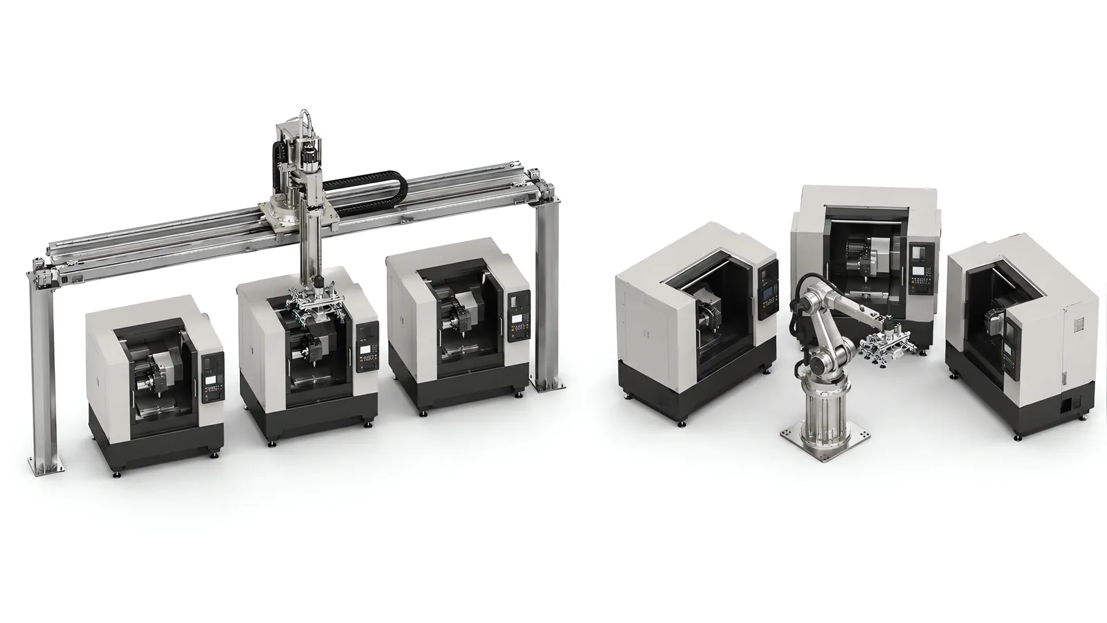
Motionwell Automation builds both sides of the gantry vs robot machine tending question in Singapore, and the answer is settled by geometry before price. Our own linear gantry series runs a welded steel single beam down the length of the row, dual Z-axis heads servicing more than ten CNC machines in parallel. On the other side we integrate industrial arms on whichever platform your plant already maintains. The arm is bought either way, and the spares, the teach pendant and the training are what you live with. What we design is the low-profile seventh axis they ride on: 100 mm of overall track height at plus or minus 0.5 mm repeat positioning, delivered on a 3 m track with 1.5 m or more of stroke and 1.5 tonnes of platform load.
Read as cartesian vs articulated robot, the choice is a question about the shape of your layout. Machines in a row favour a beam. Machines around a point favour a wrist. Machines are designed, assembled and tested at our Woodlands Link facility, and the company has delivered more than 150 special purpose machines since 2014 under ISO 9001:2015 and bizSAFE Level 3.
The wider build scope behind either choice, including machine interface signals, part presentation and swarf, is on our machine tending automation page; the arm-side work is on the robot integration services page; and the third family is our comparison of collaborative and industrial arms.
Are Your Machines in a Row or Around a Point?
This is the first question and it usually settles the shortlist, because the geometry decides everything downstream.
An articulated arm works inside a shell around a fixed base. Its reach is a radius, bought in every direction at once including the ones you will never use, and payload falls off sharply at full extension, exactly where a long layout asks the arm to work. More distance means a change of arm class.
A gantry works inside a rectangular envelope along the row. A sectional rack-and-pinion X axis can be extended to serve more machines, with beam support, drive capacity and cycle time checked for the longer route. This may avoid a second robot cell, but the extension also needs suitable guarding, access points, cables and validation.
| Geometry factor | Linear gantry | Six-axis articulated arm |
|---|---|---|
| Shape of the working envelope | A rectangular prism along the beam, sized independently in X, Y and Z | A shell around the base, sized by one reach radius |
| How you buy more distance | Add beam and rail sections; X runs on rack and pinion in modules | Change arm class, or add a linear seventh axis |
| What distance costs | Structure, drive sizing and cable carrier length | Payload, which falls off sharply at full extension |
| Axes of motion | Three, X-Y-Z across our compact, single-beam and double-beam series | Six, so the tool orientation is free at the target |
| What one unit serves | More than ten machines on a straight row, on delivered systems | One or two within reach, more on a seventh axis |
| What breaks the model | A scattered layout, or a part that must enter at an angle | Distance, because reach is the wrong tool for it |
The test takes ten minutes with a layout drawing. Mark the load point of every machine, meaning the open door and the chuck or vice behind it. Points on a line are covered by a beam, and every metre added is a module. Points on a circle around a spot where an arm could stand are covered from one base. Points scattered on both sides of an aisle suit neither, and what the drawing is telling you then is one arm per cell, or a track down one side and a rethink of the layout.
What Does a Three-Axis Gantry Give Up at the Chuck?
It gives up orientation, and that is the whole of it. Every series in our linear gantry range moves in X, Y and Z, so the part enters the machine in the attitude the gripper picked it up in. The gantry presents the part as it holds it, and cannot tilt, roll or turn it on the way in.
Where blanks come from a magazine or a fixtured tray in the attitude they have to be loaded in and drop vertically into a chuck, that costs nothing. That is the case the beam was designed for. Where it stops being free is easy to check on a drawing: an angled or tilted fixture, a part that flips between the first and second operation, or a blank that arrives lying down and has to go in standing up.
A six-axis wrist solves all three directly, which is what the extra three axes are for. Three cheaper answers are worth pricing first: change how the blank is presented upstream, put a passive flip station between the pick and the place, or bring one arm in at the single station that needs the rotation and let the beam do the transport. Which is cheapest depends on how many part numbers need the flip.
There is a second-order effect worth naming. Because the gantry cannot fix orientation later, it has to be right at the pick, which pushes cost upstream into trays, magazines and locating fixtures, while an arm can accept a sloppier pick and correct on the way in.
Which Space Do You Actually Have, Floor or Overhead?
The two consume different space, and many plants we see are short of one.
A gantry travels overhead, so the floor under the row stays clear for the operator, the pallet truck and the swarf bin, and on a tight shop that aisle is often worth more than the difference in robot price. What it needs instead is clear height along the whole row and a structure to carry it: an overhead crane, service runs, lighting, extraction ducting and sprinklers occupy the same volume, and double-beam builds add a maintenance walkway and railings on top. Anything already up there is a conflict, cheaper to find on a photograph than on site.
An arm consumes floor: its own cell area plus safe access, and on a seventh axis a corridor down the row plus its guarding. The vertical cost of a track matters too, because a conventional seventh axis eats 200 to 400 mm of vertical working height before the arm has done anything. That is why we designed ours at 100 mm overall height with ground rack and pinion, plus or minus 0.5 mm repeat positioning and no floor pit, carrying a six-axis arm as a coordinated external axis. Height taken back at the track is height the arm keeps, and on machine tending the top of the working envelope is exactly where the chuck sits.
| Space question | Linear gantry | Arm on the floor | Arm on a linear track |
|---|---|---|---|
| Floor consumed | Column bases and the guarded perimeter | Cell area plus operator and pallet truck access | A guarded corridor along the row |
| Height consumed | Beam, Z stroke and head over the full row | Arm height only | Arm height, plus 200 to 400 mm on a conventional track, 100 mm on ours |
| Conflicts to check first | Crane, ducting, sprinklers, roof structure | Door swing, chip conveyor, operator position | Floor levelling, cable carrier run, cross-traffic |
| What it costs in access | Puts the maintenance point at height | Occupies the space beside the machine door | Crossing the corridor while the cell runs |
How Many Machines Can One Unit Hold, and What Stops It Adding One More?
One steel single-beam unit with dual Z-axis heads serves more than ten CNC machines in parallel, with delivered lines running eight to ten machines from a single gantry. An arm covers one or two machines within reach, and more only on a track, where it visits machines serially the same way a beam does while still paying for a floor corridor and guarding.
What caps the number is arithmetic. One unit holds as many machines as it can complete a full tending round trip for inside the shortest machine cycle on the row: divide that shortest cycle by tending time per machine plus travel, set out in full on our machine tending automation page. Two consequences follow. A row of fast machines is harder to serve than a row of slow ones, because tending time barely changes while the window shrinks, and a mixed row bottlenecks on whichever tool finishes fastest.
This is where the dual Z-axis head earns its cost. Two independent Z columns, each carrying a gripper pair, let one column lift finished parts out while the other puts blanks in, working four parts in a single visit. Read that for what it is: one visit at each machine instead of two, which does nothing for the cutting time and everything for the round trip. Visits saved across a row is the whole of the gain, and it is visits that cap how many machines one unit can hold.
Why Compare Cost Per Served Machine Instead of Cost Per Robot?
The two do not scale the same way, so one gantry against one arm compares nothing. Machines served is the denominator that makes the two numbers comparable.
One gantry over a row comes in below deploying several six-axis robots for the same job, and the reason is structural: you buy one motion system and fence one perimeter. That holds for the work the beam is good at, a straight row of machines loaded vertically. Move any part of that premise and the arithmetic moves with it. The reason the gap exists is visible in what each option multiplies.
| Item | Multiplies with machine count on an arm-per-machine layout | Grows with row length on a gantry |
|---|---|---|
| Motion system | One arm per one or two machines | One beam, extended in sections |
| Controller and drives | One set per arm | One set, with drive sizing set by the beam length and payload |
| Tooling | One gripper set per arm | One or two gripper pairs on the Z heads |
| Guarding perimeter | A perimeter per cell | One perimeter around the row, longer, with more access points |
| Cable and energy chain | Short dress pack per arm | Full-length carrier along the beam |
| Machine interface | One per machine either way | One per machine either way |
That last row matters more than it looks. The signals a machine tool has to give a robot, and the work of getting them out of a legacy control, are a cost per machine neither option avoids, so read the comparison as being about the motion system and the perimeter.
The gantry’s shared infrastructure cost falls on fewer machines when the row is short. Over a single lathe, the beam, columns, rail and cable carrier may cost more per served machine than an arm beside the door. Compare both installed arrangements, including access and the loading sequence.
What Happens When the Shop Layout Changes?
The arm wins this one clearly, and it belongs in the comparison before the capital numbers.
A gantry is a structure sized to one row. Beam length, column positions, rail, cable carrier and drive sizing all follow the machines that were on the drawing when it was designed. Extending that row is modular, because the X axis is built in joinable sections. Moving the row is a re-installation: dismantling, re-levelling, re-aligning, re-commissioning, and whatever the guarding becomes in its new position.
An arm relocates with its pedestal and is re-taught, and a collaborative arm moves to another line and is re-taught in a shift. Our low-profile track relocates with it, because it sits on adjustable feet at 100 mm and needs no sunken pit.
Ask two questions before signing off a beam. How many times has this row been rearranged in the last five years, and is a product change coming that alters the machine mix? A shop that rearranges annually hands the capital saving back in re-installation. A row that has not moved since the building was fitted out is what the beam is for.
Which Is Easier to Maintain, and Who Has to Go Up There?
Maintenance access splits the two the opposite way from floor space, which is why it deserves more than a footnote.
A gantry keeps its mechanism above the process. Linear guides, ball screws and rack teeth collect chips, and coolant mist strips grease off them, so carrying that mechanism above the mess instead of down in it is a genuine service advantage. Where the environment is dirty we specify V-groove roller guides in place of recirculating ball guides, which is what our dual-rail truss manipulators run in dusty and harsh service, because a roller on a V edge sheds the debris a ball guide would ingest. What it costs is a service point at height. Double-beam builds carry a maintenance walkway and railings for that reason; on single-beam builds, settle at design stage whether the Z head can be driven to a service position at one end of the row.
The cable carrier is the wear item the two do not share. A carrier running the full length of the beam and filling with hot chips becomes an abrasion problem long before it becomes a jam, so it needs continuous-flex cable rated for the travel, routed away from the chip conveyor discharge. An arm has a shorter dress pack and a smaller version of the same problem, covered from the tooling side on our end of arm tooling page.
An arm keeps everything at working height and is serviced without a ladder. What it costs is standing in the floor space beside the machine door, the space the machine tool’s own technician wants when the spindle needs work, and on a row that conflict repeats at every station. Design for fault recovery either way: after a stop, somebody has to get a part out of a machine with a gripper inside it, and a Z head over an open door in an unknown state is not a trivial extraction.
Why Is the Robot Idle Most of a Long Cycle, and Why Is That Correct?
Machine tending is the application where an idle robot is the right outcome, and misreading it is a common reason a sound project gets rejected.
The machine cycle sets the pace, and the robot’s only job is to finish its round trip inside that window, so on a long machining cycle it waits by design. That waiting is not waste. It is the headroom that lets one unit cover a row, and it is what you are buying when you buy a beam. An arm dedicated to a single machine converts the same idle time into nothing, which is why either layout is judged on machine utilisation and unattended spindle hours, never on how busy the robot looks.
The comparison to run is therefore not top speed but tending time per machine plus travel, timed against the shortest cycle on your row. Where tending time itself is the constraint, the row has outgrown a single unit of either kind, and the answer is two units, a resequenced row or a buffer.
When Is a Gantry the Wrong Answer?
A scattered layout or machines on both sides of an aisle can leave a gantry carrying long stretches of structure between useful stops. A short row creates a different cost problem: beam, columns and cable carrier are shared by only one or two machines. These layouts merit a comparison with pedestal-mounted arms or a standard tending cell from the machine tool supplier, including the available access and loading direction.
The other two geometric stops are attitude and headroom. Angled chucks, tilted fixtures, a flip between operations or a part that must be set down differently from how it was picked all need a wrist, because three axes present the part as they hold it and no amount of travel substitutes for rotation. And an existing crane over the row is a hard stop, as are ducting, sprinklers and a roof structure that will not carry a beam. Both are cheaper to find on a photograph than on a concept drawing.
Two more are about change over time. A layout that will move hands the capital saving straight back in re-installation, and it is the failure that surfaces two years after acceptance, never at handover. A mix that changes faster than the parts does the same thing through changeover: where changeover cost dominates cycle time, a reprogrammable loading device beats a faster one. On our cleanroom automated test equipment build a dedicated gantry would have been quicker per cycle and was still the wrong machine, because mixed connector types and modest volume per variant meant the loading device had to be reprogrammable. A collaborative arm was specified instead, holding plus or minus 0.05 mm at the fixture interface, and the reasoning is set out in the cleanroom test equipment case study.
The last three say the job belongs to a different machine entirely. Work that follows a path, meaning grinding, deburring, dispensing along a contour and anything carrying a process force, is six-axis work; our own example is force-controlled robotic grinding of CFRP composite panels holding 100 N constant contact force, developed with A*STAR SIMTech, and a three-axis frame has no way to hold a tool normal to a curved surface. Light, planar parts moving very fast are SCARA work, because metres of straight travel are cheaper and stiffer on a cartesian frame while a short, fast, flat pick and place is neither machine on this page, as our SCARA robot selection guide sets out. And blanks tipped loose into a bin are a perception project sitting on top of the motion project, needing its own proving trial on your own parts; our delivered picking is from fixtured, taught or vision-corrected positions, and tray or magazine presentation upstream is usually the cheaper way to get there.
Is a Hybrid Layout the Better Answer?
Often it is, and it belongs on the shortlist as a third option. The pure forms are the ends of a range, and many of the rows we are asked to quote sit inside it.
| Hybrid shape | What it fixes | What it costs |
|---|---|---|
| Six-axis arm on a low-profile linear track | Distance without giving up the wrist; the arm serves several stations outside one envelope | A guarded floor corridor, and vertical height unless the track is a low-profile design |
| Gantry for the row, one arm at the station that needs rotation | Keeps the cheap transport and buys orientation only where it is needed | An interface between two motion systems, and someone has to own it |
| Gantry with a passive flip or regrip station | Orientation change with no second robot | A fixture per part family, and cycle seconds at the flip |
| Gantry serving the machines, arm serving the awkward pose at the end | Long rows that finish in an operation the beam cannot present | Two safety zones, and a handshake across them |
The first row is the one often left out of a two-way comparison. Buying a bigger robot to cover distance usually costs more than putting a normal robot on a track, and it does nothing for the multi-station case. Our track was designed for that job: 100 mm overall height so it does not eat the arm’s usable envelope, ground rack and pinion at plus or minus 0.5 mm repeat positioning, and integration as a coordinated external axis on the arm’s own controller, so track motion is planned with the arm. That distinction is worth checking in any seventh-axis quotation, because an axis sequenced after the arm adds its travel to every single move, while a coordinated one overlaps it.
Two conditions decide whether a hybrid earns its extra interface. The work must be genuinely separable, which is a process question. And somebody must own the handshake between zones: part present, zone clear, station ready, fault. An interface is where two suppliers can each assume the other owned it.
What Changes in the Safety Scope Between a Beam and an Arm?
The standards are the same for both. Start from an ISO 12100 risk assessment; the robot and the integrated system then fall under ISO 10218-1 and ISO 10218-2, with each safety function carrying a required performance level under ISO 13849-1, calculated and validated.
What differs is the shape of the guarded space and the hazards inside it. A gantry guards a long perimeter: fence length follows the row, and every point where an operator loads a magazine, clears chips or reaches a machine control is an access point to interlock or scan. It also carries a hazard the arm does not: a load travelling overhead where people stand. Where the machine incorporates lifting equipment it must be certified by an approved authorised examiner before use in Singapore. An arm guards a compact envelope with one or two access points, which on a track becomes a corridor with cross-traffic to manage. Scanner distances are calculated, from the ISO 13855 approach speed constant of 2,000 mm/s up to 500 mm and 1,600 mm/s beyond, plus stopping performance measured on the built cell.
One point applies to both and is easily missed: the machine tool has its own door interlock and stop category and the cell has its own, so somebody must own that boundary and prove the robot cannot enter while the spindle can turn. Singapore does not require CE marking, but the Workplace Safety and Health Act requires dangerous parts of machinery to be securely fenced. We deliver the guarding scope that follows either choice, described on our machine safety and CE marking page.
Which One Should You Specify?
Run these in order. The first that gives a hard answer usually settles it, and where two disagree the answer is normally the hybrid above.
- Where do the load points sit? Mark the open door and the chuck for every machine. A line points at a beam, a circle at an arm, a scatter at neither.
- Does the part change attitude between the pick and the place? If it does, either buy the wrist or design the flip, and price both.
- What is above the row? Clear height, with the crane, ducting and sprinklers counted in. This one is a hard stop.
- How many machines, and what is the shortest cycle among them? Machines served is that shortest cycle divided by tending time plus travel, and it is what makes cost per served machine mean anything.
- How often does this layout change? Annual rearrangement argues against a fixed structure regardless of everything above it.
- How many part families share the row? High mix with frequent changeover moves the argument towards a reprogrammable arm.
- Who services it, and how do they reach it? Work at height on a beam, floor space beside the door on an arm.
| Your situation | Start from | Why |
|---|---|---|
| Straight row of machines, parts load vertically, layout is stable | Linear gantry, dual Z head where the row is long | Distance is cheap on a beam, and the floor stays clear |
| One or two machines, floor space available beside the door | Six-axis arm | Cost per served machine has no denominator to work with |
| Several stations outside one reach, parts need orientation | Six-axis arm on a low-profile linear track | Distance without giving up the wrist |
| Angled fixtures or a flip between operations, on a long row | Gantry for transport, arm or flip station for attitude | Buy orientation only where the process needs it |
| Crane, ducting or roof structure fills the space above the row | Six-axis arm, on a track if the row is long | Overhead volume is a hard constraint |
| High mix, changeover dominates cycle time | Reprogrammable arm, collaborative where a person stays in the loop | Reprogrammable beats quick when the mix changes faster than the parts |
| Process force along a contour | Six-axis arm | Three axes cannot hold a tool normal to a curved surface |
| Row is likely to be rearranged within the machine’s life | Six-axis arm, or a gantry costed with re-installation in it | A beam is sized to the row it was drawn for |
Lead time runs 16 to 24 weeks from concept approval to factory acceptance testing on a standard build. Design, fabrication, assembly and testing happen at Woodlands Link with an in-house design team of eight, which is why a Singapore buyer attends the factory acceptance test without flying to it. That matters on tending work, because the details that decide whether a cell runs are gripper and fixture details found on your own parts. The delivered gantry work sits in context on our warehouse and intralogistics page.
Standards Used in Machine Design and Validation
These references inform the design, testing and documentation described on this page. Each row links to its primary source and records the edition checked.
| Standard | Current edition | What it means for your machine |
|---|---|---|
| ISO 10218-1: Robotics, safety requirements, Part 1: industrial robots | ISO 10218-1:2025 | Published February 2025, the third edition and the first substantive revision since 2011. It adds robot classifications with matching functional safety requirements and safety-related cybersecurity requirements. Most of ISO/TS 15066:2016 on collaborative operation moved into Part 2.Checked 12 Sep 2026 against ISO 10218-1:2025 (iso.org/standard/73933.html) |
| ISO 13849-1: Safety of machinery, safety-related parts of control systems | ISO 13849-1:2023 | Provides the design method for safety-related control functions, including architecture, component reliability, diagnostic coverage and common-cause failure measures. The machine risk assessment establishes the required Performance Level; design calculations and validation provide the evidence for each function.Checked 1 Sep 2026 against ISO 10218-1:2025 normative references |
Frequently Asked Questions
Is a gantry really cheaper than several six-axis robots?
On the job a beam is good at, a straight line of machines loaded vertically, yes, and the framing matters: one gantry over a row buys one motion system, one set of drives, one tooling set and one guarded perimeter, where an arm per machine or two multiplies all four. That is an engineering trade, and it is not a quotation for your row. Cost per served machine is the number worth comparing. A beam over ten machines divides its cost ten ways; a beam over one machine divides it once, and there an arm usually wins.
Can a three-axis gantry load a part into an angled fixture?
Not as it stands. Every series in our linear gantry range moves in X, Y and Z, so the part enters the machine in the orientation the gripper picked it up in. If the chuck sits at an angle, if the part flips between the first and second operation, or if blanks arrive lying down and have to go in standing up, that orientation change has to live somewhere: in how the blanks are presented, in a passive flip fixture, or in an articulated arm at the one station that needs it. A six-axis wrist buys the freedom directly, and pays for it in reach.
What happens to a gantry if we rearrange the shop floor?
You re-install it, and this is the clearest advantage an articulated arm holds. A gantry is a steel structure sized to one specific row: beam length, column positions, rail, cable carrier and drive sizing all follow the machines that were there when it was designed. Adding two machines to the end of a row is a modular extension. Moving the row is not. An arm on a pedestal relocates and is re-taught, and our low-profile linear track is 100 mm high on adjustable feet with no floor pit, so it travels with the arm. If your layout changes yearly, weigh that before the capital comparison.